I have seen a site similar to the classic, but darlington transistor-quality hifi amplifier circuit. very few elements with the less clean up audio element that account. the beautiful thing about all the details, there is a list of the schema, pcb, set of illustrated information on the flow of material, calm, etc..
100W amplifier circuit +-42v power supply 100W RMS with a symmetrical 2x42v so the music power 140w but watch out on the poor quality of the writer can burn the last sound speaker 100w küçümsenebilir 250w exaggeration may not remove at the RMS value of the speakers 100W RMS, so use the speaker volume for example some hoparlarlörde 200w rms 20w, etc. on the corner on the shore, but the author author
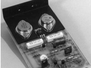
The output transistors 1 x ON709 and 1 x BDX88C transistors instead of this it will be difficult to find cover for TO3 T8 NPN BDW83C or TIP142 for BDW84C or TIP147 can be used to correspond to the T9 PNP transistors SOT-93 case is to use a larger heatsink and thermal imager (thermal paste, cream etc etc..) using the cooler isolator mount using
Serenity is the current setting for the T8 kollaktör and connect it to the “P” 10 k + in order to feed between the adjustable resistor ampermetrede 50ma set until you see.

100W Darlington Amplifier Circuit Technicial Specifications:
Sine power ………………………….. 100 W
Music power ………………… 140 W
Speaker impedance ………………… 8-ohm
Distortions at maximum power .. 0.1%
Supply voltage ………… symmetrical +-42v
Maximum power consumption ….. ….. 1.8A
Standby current…. 50mA
Frequency range ….. 20 Hz – 30 kHz 1 dB
Signal-to-noise ratio ………………….. -95 dB
Maximum input signal ………………… 1V
Required components:
R16 …….. 1 kohm 1/4W
R17 …….. 0.33ohm 5W
R18 ……… 0.33ohm 5W
R19 ….. 6.8ohm 2 to 5W
P trimmer-potentiometer 10k
CAPACITORS AND COILS:
C1 ….. 6.8mF 25V tantalum electro
C2………….. 47mF, 16V elko
C3 ………………….. 150 pF block
C4 ………………….. 150 pF block
C5 …. 180 nF (184K) 63V block
C6 …. 180 nF (184K) 63V block
L. 10 turn of f 1mm CuL wire across resistor R19
TRANSISTORS:
T1 ………….. BC547
T2 ………….. BC547
T3 ………. 2SA1293
T4 …BDT95,TIP31C
T5 .BDT95, TIP31C
T6 ……….. BC547
T7 …….. BC557
T8 ………….. ON709
T9 BDX88C, BDX65B
DIODES:
D1 …….. 1N5059
D2 ……… 1N5059
ZD .. ZPY9,1 1,3W
RESISTORS:
R1 .. 10 kohm 1/4 W
R2 .. 680 ohm 1/4W
R3. 4.7 kohm 1/4W
R4. 8.2 kohm 1/4W
R5. 330ohm 1/4W
R6 ……….10ohm 1/4W
R7. 100 kohm 1/4W
R8. 39 kohm 1/4W
R9 1.2kohm 1/4W
R10 2.7kohm 1/4W
R11 1.2 kohm 1/4W
R12 … 100 ohm 1/4W
R13 … 470ohm 1/4W
R14 … 470 ohm 1/4W
R15 ….. 1 kohm 1/4W
PCB, schematic etc. all files;
Source: mikroe.com/sr/magazine/1broj/1broj8.htm


ETD59 TL494 13.8V 40A Switch Mode Power Supply
13.8V 40 Amp “switch mode power supply” SMPS circuit ATX power supply structure was inspired by a more powerful version could be called the primary solid in the driver transistors, BJTs instead of MOSFETs used driver transformer the etd29 secondary section TL494 is controlled by a circuit over current, over temperature protection have a current detection at current transformer is used at the output of the lm339 circuit line can be used for similar applications. 13.8V 40A SMPS circuit’s bill of materials, PCB drawings, layout information, etc. transformer. given everything ..
could you please give the unlock zip file code?
Hi,
Pass: 320volt.com
I wanted to unzip : LINKS-18667.zip and guess what? A password protect zip file without further notice on how to get it? Let it be, don’t need nor want it anymore. Stick it where the sun doesn’t shine.
Hi, just a click away 🙂
pass: 320volt.com
Hello, DIYers.
How to build this amplifier?
Because there is no list of components.
SLTS
J.Tanski
Hello,
open “1broj8.htm” file