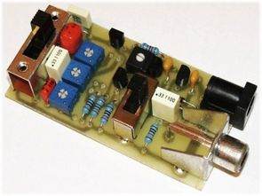
Sine wave generator circuit can be used in various test jobs. There is a bill of materials and pcb drawing of the supply voltage 9 volt circuit based on BCXXX series transistors and passive components.
Low distortion sine wave generator The design of the low frequency harmonic sine signal generator is designed to measure and revive low frequency amplifiers.
The following structure of the low frequency harmonic signal generator is created for the needs of reviving and measuring low frequency amplifiers and other circuits operating in the audio band. The circuit is used in conjunction with a low frequency (milli) voltmeter, oscilloscope or distortion meter and provides invaluable assistance in checking and revising all levels of an amplifier chain.
Basic features:
Reproduced frequencies: 300 Hz, 1 kHz and 3 kHz
Maximum Output Harmonic Distortion (THD): 0.11% at 1 kHz, 0.23% at 300 Hz, 0.05% at 3 kHz
Power consumption: 4.5 mA
Selectable output voltage amplitude: 0 – 77.5 mV, 0 – 0.775 V RMS
The circuit is based on a simple two-transistor oscillator that provides high frequency and amplitude stability. In the basic connection, the circuit does not require classical stabilizing elements such as bulbs, thermistors or special circuits to limit the amplitude.
The three output frequencies, i.e. 300 Hz, 1 kHz and 3 kHz, are selected by switch S1. The amplitude of the output signal can be continuously varied in two ranges according to the setting of switch S2 using the resistor adjuster (or potentiometer) R15. Available ranges are 0 – 77.5 mV RMS (219.7 mV rms) and 0 – 0.775 V RMS (2.191 V rms). With regulation, it is possible to obtain a stable output voltage according to the requirement of a particular application.
Parts list
R1 12k
R2 2k2
R3,R4,R5,R15 1k rectifier PK50
R6,R7 1d5
R8 1k
R9 4k7
R10 3k3
R11 2d7
R12 300R
R13 100k
C1 22n MKT
C2 3u3 MKT
C3 330n MKT
C4 56n MKT
C5 330n MKT
C6, C7 100n
D1,D2 1N4148
T1,T2,T3 BC337
IO1 78L05
J1 CINCH to PCB
J2 DJK02 (GME: K375A)
supply voltage can be in the range of 8 – 15 V, for example from a classic 9V plate battery and is fed to connector J2. In order to maintain a stable amplitude of the output signal, the voltage is further stabilized by the 78L05 circuit, which provides a voltage of about 6.2 V thanks to diodes D1 and D2.
Before starting up for the first time, it is necessary to connect the output of the generator to a counter or an oscilloscope and set the exact output frequencies to 300 Hz, 1 kHz and 3 kHz using the resistor adjusters R3, R4 and R5. If necessary, if the range of the mentioned trimmers is not sufficient, it is possible to further adjust the values of the resistors R6 to R8.
The mentioned design of the harmonic sine generator provides a very high quality and stable signal for basic measurements and matching.


Frequency range: 300 Hz, 1 kHz and 3 kHz
Max. noise ratio (THD) above 3kHz: 0.11%-1kHz, 0.23%-300Hz, 0.05%-3kHz
Low power consumption: 4.5 mA
Output voltage: 0 – 77.5 mV, 0 – 0.775 V RMS


PIC16F877 Experiment Board Circuit PIC Programming PIC Tutorial Book
A useful test development PIC16F877 circuit pcb printed circuit board design was quite nice small in size but has a lot of features. Serial RS232 connection, sensors, servos, PWM, I2C connector and so on. Experiment card with eagle schematics and PCB files are prepared. In addition, “the PIC Tutorial Programming” free ebook called shared.