You can also use your CNC project running from the computer’s LPT port interface control card to the 74HC14 integrated circuit uln2803 are based on the opto-isolation provided by pc817
I decided to design your own master plate for CNC applications but not only 😉 (it is also used as a programmer for ATmega microcontrollers, as well as an early tester of simple programs control data output LPT port written in C + +)
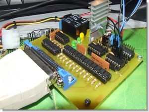
CNC control interface board

There are 4 signal LEDs in the system, two of which give information about the presence of voltage 5 (LED1) and 12V (LED4). The next two indicate that relay 1 (LED2) and 2 (LED3) are working.
EXPLANATION OF BEGINNINGS:
– JP1-JP9;JP10,11,15,13,12; JP14,JP16,JP17 – outputs /LPT inputs respectively
– JP10; JP11 – 2x6GND designed for outputs from LPT port
– JP20 – ULN inputs (pins 1 and 2 control relay 1 and 2 respectively, while the other six inputs can be used any way)
– JP21 – ULN outputs
– JP12 – voltage connector 4x + 5V (eg to power controllers)
– JP12 – additional connector 4x GND (eg for powering controllers)
– X1 – 12V power input
– X2 – relay 2 connector
– X3 – relay 1 connector


CNC interface board circuit schematic etc. files:
Password: 320volt.com
Published: 2010/02/16 Tags: motor control circuit, motor driver circuit
TDA1514 2X50Watt High Performance HiFi Amplifier Circuit
TDA1514 alone can provide 50 watts of power supply voltage and a maximum of + – 30 volts mute / stantby temperature protection, overcurrent protection feature. Amp circuit with a few passive components can