PIC16F84 speed calculation circuit 16f84 based on the software assembly-crafted in the speed measurement as a sensor LDR used sensors aralara of the object in the transition delay by calculating the display on the instantaneous speed writes pic assembly asm code and protel prepared by the printed circuit board files available
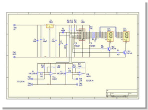
This is the circuit for the Amphometer


AMPHOMETER Project
This project is used to measure the speed of a passing vehicle. Usually, this is accomplished by having two rubber strips along the road that actuate the mechanical switches when passed over. The time it takes for the two switches to operate is used to determine the vehicle’s speed. A slightly different approach is used here. Two Light Dependent Resistors (LDRs) are used for sensors. As the vehicle passes over these devices, the circuit detects the change in current. light level. A PIC 16F84 then calculates the speed from the time difference.
The circuit is pretty simple. Two comparators are used to detect the change in voltage. It is produced when the light level changes in LDRs. Two potentiometers are used to adjust.
The light level threshold to change the comparators’ output state. When outputs, the PIC detects it and calculates the speed based on the time it takes to switch. changes that will occur. The result is displayed on a two-digit multiplexed display. The result is also stored and exported to EEPROM for later use if necessary.
If the ‘READ’ button is pressed when the unit is first turned on, the screens will show the status. from the comparators. ‘S’ for sunny and ‘C’ for cloudy. Adjust the two chambers so that the screens are the same. On the verge of going from ‘S’ to ‘C’. The unit is now ready for use.
Turn on the power and press the ‘RESET’ key. The unit will be waiting for the comparator to change. When both comparators change, the PIC will display the speed result. If power is turned off, then after restore, the last reading is always available by pressing the ‘READ’ key.
For the unit to work properly, the sensors must be placed within two meters of each other. These sensors are made of approximately 10 cm square perspex pieces with 4 mm holes drilled in their centers. These LDRs are mounted in these holes by fixing the wires to the back face.
PCB layout is in Protel Autotrax format.
Amphometer Circuit PIC16F84 Measure the Speed schematic protel pcb and assembly source code files:
Password: 320volt.com
Published: 2009/01/29 Tags: microchip projects, microcontroller projects, pic assembly example, pic16f84 projects
PIC16F84 DS1920 Scrolling Temperature Display MAX7219 CCS C
Pic16f84 LED display with temperature measuring software compiled with CCS C
Scrolling Temperature Display. -55 – 100C (-67 – 212F) range 4 digit LED display compile-time animation options
This project shows a temperature readout on a 4-digit LED display. The temperature shown scrolls between Centigrade and Farenheit; compile time options allow for a display which scrolls in one direction or “bounces” from side to side.