2 for two different transistor pcb printed circuit crafted case you can use the appropriate
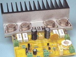
Transistor 2N3055 and MJ2955 Used in metal sheath version TIP3055 and the plastic-type metal-sheathed version is more powerful than TIP2955 size and structure, but with better heat transmission cooler installation more difficult.
Circuit 8Ω speaker with 50W RMS 4Ω speaker with a 70w rms power can give THD noise ratio is very low 003% of the circuit Operating the for the symmetric 2x40v dc power supply is required VR1 potentiometer with a quiescent current is adjusted input audio signal without connecting diagram Q5 transistor collector and-40v inter-38.2v measure until potentiometer should be set up in key areas that need to be already in the schematic drawing given voltage. Power supply from the AC supply circuit 150w transformer for use 2x28v


Hi-Fi Amplifier Performance
Output Power: 50 watts into 8ohm 70 watts into 4ohm
Music Power: 77 watts into 8ohm ;105 watts into 4ohm
Frequency response: -1dB at 14Hz and 70kHz
Input sensitivity: 0.875V for 50ohm into 8ohm
Harmonic distortion: <.05% from 20Hz to 20kHz; typically <.003%
Signal-to-Noise Ratio: -114dB unweighted (22Hz to 22kHz); -119dB A-weighted, both with respect to 50W into 8ohm
Damping factor: >140dB at 100Hz &1kHz, with respect to 8ohm and without PTC thermistor
Protection fuses plus: “Polyswitch” PTC thermistor Stability unconditional
50w RMS Amplifier circuit’s PCB schematics, layout files:
Password: 320volt.com
Published: 2008/01/22 Tags: audio amplifier circuits, transistor amplifier
145W Balanced Darlington Transistor Amplifier TIP142 TIP147
Darlington Amplifier Used in the output stage power transistors TIP142 and TIP147 4 can be found in all parts 8Ω 145W 4Ω speaker with market power can give 275W two-channel stereo whether you can use the same circuit two. Anfi circuit total of 100 volts dc supply voltage symmetrical 2x50v
Circuit quiescent current adjustment circuit low voltage automatically adjusted (2x25v) If you want to run with 0.22Ω 0.33Ω resistance must change 4w
TIP142 TIP147 Amplifier Circuit
2 für zwei verschiedene Transistor-PCB-gedruckte Schaltung gestaltete Fall können Sie die entsprechende verwenden
Transistor 2N3055 und MJ2955 Wird in der Metallummantelungsversion TIP3055 und in der Metallummantelungsversion vom Kunststofftyp verwendet und ist leistungsstärker als die Größe und Struktur des TIP2955, jedoch ist die Installation eines Kühlers mit besserer Wärmeübertragung schwieriger.
Schaltung 8Ω-Lautsprecher mit 50W RMS 4Ω-Lautsprecher mit 70W RMS-Leistung können THD-Rauschabstand ergeben ist sehr gering 003% der Schaltung Betrieb des für die symmetrische 2x40V-Gleichstromversorgung erforderlichen VR1-Potentiometers mit einem Ruhestrom eingestellten Audioeingangssignal ohne Verbindung Diagramm Q5 Transistorkollektor und -40V Inter-38,2V messen, bis das Potentiometer in Schlüsselbereichen eingerichtet werden soll, in denen bereits in der schematischen Zeichnung die angegebene Spannung vorhanden sein muss. Stromversorgung aus dem Wechselstromnetz 150W Transformator für die Verwendung von 2x28V