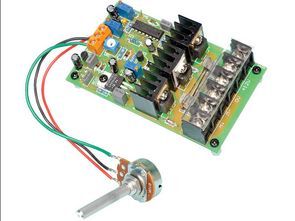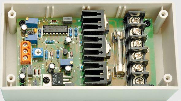
In the circuit prepared for DC Motor speed control (mk2) TL494 pwm control integrated circuit is used. There are 2 IRF1405 N-channel mosfet transistors at the integrated outputs. Speed adjustment is adjusted with a 10k potentiometer and frequency adjustment is adjusted with 100k. 12 volt or 24 volt dc motor can be used. TL494 Speed control range is between 0/100%, idle current draw is 20mA power max. 20 amps also has the feature of detecting when the voltage of the connected source (battery etc.) is low.
12V 24V 20 aMPER DC Motor Speed Controller Main Features
• 20A current rating
• 12V or 24V operation
• Internal trimpot or external potentiometer for speed adjustment
• Optional soft start soft start 0-100% approximately 1s
• 0-100% speed control range
• Efficient PWM control
• PWM frequency adjustment ~ 100Hz – 1.1kHz (129Hz – 1.28kHz measured on prototype)
• Low battery protection
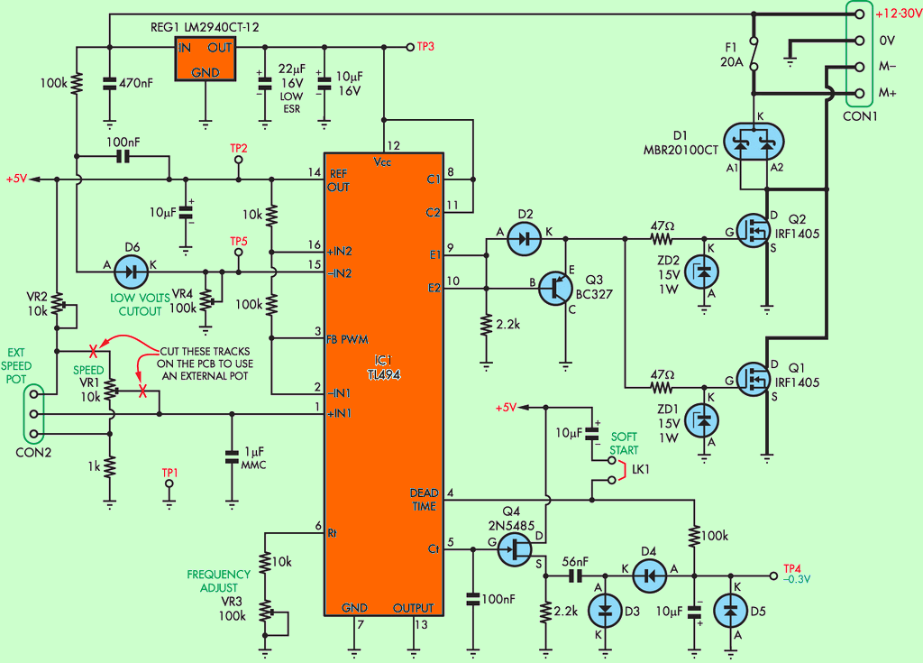
The 20 amp motor control circuit is based on a TL494 Switch Mode Pulse Width Modulation (PWM) Control IC. External timing components RT and CT on pins 5 & 6 set the PWM frequency, while the IRF1405 controls the output transistors Q1 and Q2.
DC Motor Speed Control Circuit Diagram


Since the speed control circuit works with pulse width modulation, when the pulse width changes the voltage supplied to the motor, this can make the motor produce more noise. This is due to the magnetostriction of the core laminations and the blocking of the armature windings. You can reduce this lamination noise by changing the pulse frequency, and there is a trimpot (VR3) on the PCB to provide this feature.
As mentioned above, we have provided low battery protection. This is mainly to prevent damage when the circuit is powered from a 12V lead acid (SLA) battery, which will completely die if it is discharged below 11V.
Soft-Start is also included in the circuit. This will slowly accelerate the motor when power is connected to the circuit, regardless of the speed setting. If soft-start is not required, it can be disabled by removing a jumper connection.
Source: http://www.siliconchip.com.au/cms/A_112476/article.html alternative link:
Şifre-Pass: 320volt.com
Published: 2011/08/11 Tags: motor control circuit, motor driver circuit, pwm circuits, tl494 circuit
USB Powered Inductance Meter Circuit Atmega8
Coil measurement “Inductance Meter” circuit based on Atmega8 microcontroller LCD HD44780 driver and the system’s power supply is taken from the USB port on the computer or adapter operated with the circuit. Circuit of the box mints box cut and processed interesting metal, enamel paint made circuit optimized 🙂
The LCD screen of the circuit 10MHz frequency coil over strut value is displayed in the Information, as well as the frequency.