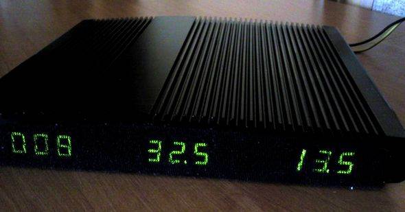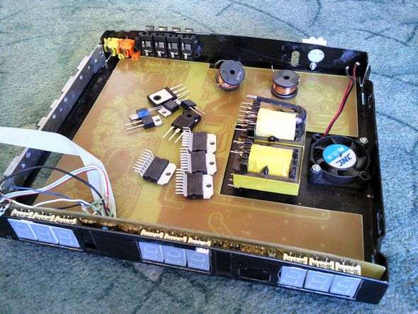
Car amplifier project 4 TDA7294 used per channel 100w gives total 400w amplifier circuit supply TL494 PWM control integrated with the SMPS section retrieving circuit Additionally watts, voltage, temperature information indicating ATMega8 made with digital tokens.
TDA7292 SMPS ATMega8 on a single PCB and display on a separate PCB’s source code and all PCBs have drawings.


Power amplifiers
The power amplifiers are simple, cheap and widely available TDA7294 integrated circuits. Theoretically, each has a power output of 100W. The power I measured (effectively) is equal to 85W per channel – with 1% distortion. The terminals operate in a standard application with slightly modified control of the ST-BY and MUTE lines for faster terminal closure after power is removed.
A 1N1418 diode has been added to the MUTE line for this purpose. The cubes are dual-controlled, with channels A and B, as well as C and D, having common ST-BY and MUTE lines. Why? Because they can operate in a bridge configuration, and it is good if they are turned on and off at the same time. On the board, next to the pin connectors for the input signal, there are jumpers with which you can quickly reconfigure the terminals for bridge operation, so you can bridge channels A with B and channels C with D.
To do this, the signal should be supplied only to the first channel (A or C), and on the second channel (B or D) two jumpers should be placed on the marked jumpers (“bridge A+B”, “bridge C+D”), one on the pins with the input signal, and the other on two neighboring pins, through which the inverted signal will flow from the output of the first terminal to the input of the second. Of course, after such an operation, the speaker must be connected correctly.
In addition, the board has a low-pass filter with a cut-off frequency of about 80 Hz. It can be used freely, for example, the signal from its output is fed to the bridged channels, and they can be used as a subwoofer output. It works with +12V -12V.
Front panel meter and current measurement
The meter is based on the Atmega8 microcontroller with a program written in bascom. The microcontroller controls the LED displays by multiplexing – that is, only one display is lit at a time. Therefore, the displays are weakly lit, so the resistors limiting the segment current should be as small as possible – the diagram shows a safe value of 100ohms, in my case 39ohms.
It is good to choose them according to the maximum instantaneous current that our display can accept – see the note. Digital sensor, temperature measurement performed on the popular DS18B20 – I had some problems with reconciling multiplexing and 1-wire communication for this sensor, since the interruption usually interferes with the transmission, but “somehow” it works 🙂 Voltage measurement via a 100K precision potentiometer connected right next to the power terminals and working as a voltage divider, and together with a 100uF capacitor, it forms an RC filter that averages the measurement result.
The divider is set to obtain 5V for the ADC at 17V at the input. Current measurement performed by measuring the voltage drop on the measurement path, measurement on the ground (ground path between capacitors C11 and C12):
Şifre-Pass: 320volt.com
Published: 2011/06/10 Tags: atmega8 projects, audio amplifier circuits, dc dc converter circuit, ic amplifier, tda7294 amplifier circuit, tl494 circuit
Sanyo STK Amplifier Schematics
Sanyo production STK series power amplifiers integrated belonging to the original circuit diagrams diagram of the manufacturer (SANYO) is the problem will not be a market original NGO integrated hard to find even copy the original design made in accordance with the general power transistors low quality but fake though a lot amp integrated from the transistor from Anfi etc.. gives a much better sound.
STK Amplifier Schematic list