Tag: tl494 circuit
AT PC Power Supply Circuit Schematics
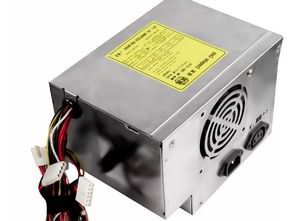
AT power supply circuit diagrams for AT computer systems. Very old structure ATX system was soon removed from the market after its release but archive is also available. Lunar 200 AT Power Supply Schematic Moretec MP200 AT Power Supply Schematic PW9502 AT Power Supply Schematic SKS4230 AT Power Supply Schematic TYET005V0 AT Power Supply Schematic…
TL494 DC CDI Ignition Circuit AT-ATX Transformer
For most people interested in capacitor discharge ignition, the repeatability of DC-CDI is difficult and they have little experience with winding transformers. This design uses an AT-ATX PC power supply transformer for voltage conversion. There is no need to wind the transformer. The necessary transformer can be obtained from old-style PC power supplies. TL494 or…
1800W 36VDC Electric Bike Motor Driver Circuit TL494
The motor driver circuit controlled by TL494 PWM IC is 36V 864W and its maximum over-power is 1800W. Lithium-ion (Li-ion) batteries are used for the power supply. Ten cells are used in series to ensure that the battery voltage is close to the nominal voltage of the motor, thus creating a source with a nominal…
12V 20A Lead-Acid Battery Charger TL494 UC2906 ACS758
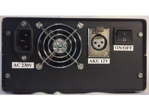
The designed SMPS charger system uses both constant current and constant voltage charging methods. It can be used to charge classic, gel and traction accumulators with a working voltage of 12 V. It can gently charge deeply discharged accumulators, but also maintain their maximum capacity during a longer shutdown. The charger is able to recognize…
0.2V-80V 0-10A Adjustable Switched Mode Power Supply
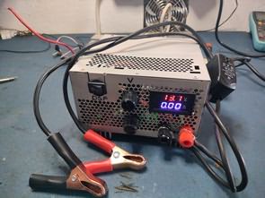
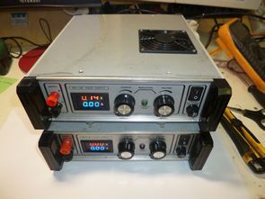
The 0.2V-80V switched power supply built on TL494 Integration can be used in various devices, motors, battery, battery charging processes, etc. designed for. There is additional SMPS circuit with TNY267 integrated circuit for feeding elements such as TL494, Fan, Relay. Like many circuit elements used in the SMPS Project, this material was supplied from PC…
Scooter Motors Control Circuit 500W TL494
350W Scooter of Electric Motor Scooter control unit, max. It can power 500W. Input voltage 36V DC (can be used with 20V… 50V.) Scooter Motor Control works on the principle of motor winding as a switched power supply and coil. In forward driving, the unit acts as a downstream converter and controls the current to…
TPS92513 TL494 Power Led Driver Circuit
Design of controllable current source, which will be used to control the brightness of the power LEDs. It is intended to use fifteen PWM outputs from Arduino for management of fifteen resources. This application will be used to calibrate the camera. That’s why it is minimum ripple current through the LEDs is required. At the…
TB6560AHQ ATMEGA64 CNC Projects
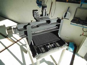
The subject of this project is realization of CNC milling machine, designed for production of smaller machines light alloy and PCB components. This will be subject to selection of mechanical components and drive. The mechanical construction should not be too complex due to limited production means, however, a laser cutter is available and the possibility…
Adjustable Switch Mode Power Supply 0.25V 0.5A TL494
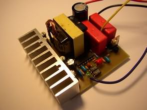
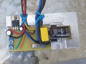
Switch Mode DC DC Adjustable Power Supply The TL494 system is the heart of the stabilizer. Elements C13-1.5NF, R14-10K set the frequency of the internal generator work to about 77 kHz. Comparator first, along with elements R7, R8, R9, R15, R16 and C14 are the output voltage stabilization circuit, which the value is regulated by…
