Tag: smps schematic

SMPS Circuits, SMPS Projects SMPS stands out, Switch Mode Power Supply There are basically 3 types of buck converter, boost converter and lowering-amplifier converter.

Switching Power Supply 2X40V Active PFC 400V

| 2024/12/17

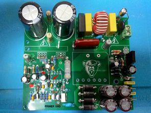
Active PFC supported SMPS power supply is made with IR2156 Ballast driver integrated circuit. Active PFC section uses MC33262 active power factor integrated circuit. Output voltage of SMPS circuit on load is 2X40VDC PFC output voltage is 400V There is source PCB drawing of Active PFC Power supply project (sprint layout 6) also MC33262 PFC…
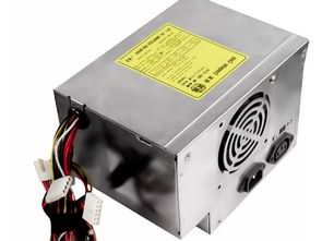
AT PC Power Supply Circuit Schematics

| 2024/12/17

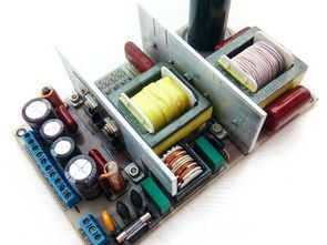
AT power supply circuit diagrams for AT computer systems. Very old structure ATX system was soon removed from the market after its release but archive is also available. Lunar 200 AT Power Supply Schematic Moretec MP200 AT Power Supply Schematic PW9502 AT Power Supply Schematic SKS4230 AT Power Supply Schematic TYET005V0 AT Power Supply Schematic…

ATX Transformer Simple Switch Mode Power Supply Self Osc SMPS V2

| 2024/12/17

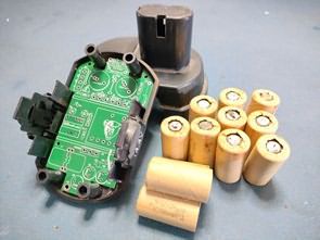
I prepared a PCB for the Simple Switch Mode Power Supply Self Osc ATX Transformer that I shared before. It is compatible with the battery boxes of many drills. Apart from the PCB design, the tests were very challenging, I encountered interesting problems and saw strange events especially in electronics repair work. The problem of…

2X38V 250W IR2156 Amplifier Power Supply SMPS

| 2022/10/27

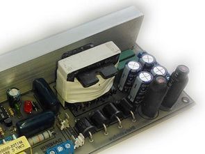
An SMPS switched power supply project for power amplifiers with the IR2156 half-bridge mosfet driver IC from International Rectifier (currently acquired by Infineon Technologies). Brief information about IR 2156. The IR2156 is a half-bridge half-bridge converter controller with a built-in high voltage driver and a programmable oscillator. It was designed by the manufacturer as a…

1200W 60V SMPS Circuit UC3844 150Khz

| 2022/07/01

1200W 60V SMPS Power supply UC3844 Classic topologies of blocking converters are usually considered suitable only for small ones performance, on the order of about 100-200 W. Their main advantage for low-power applications is simplicity and large input voltage range. At the output of the transformer only the rectifier diode and the output capacitor are…

Simple Switch Mode Power Supply Self Osc ATX Transformer

| 2022/07/01

Simple SMPS Circuit Self-Oscillating ATX Transformer There were shares to run the rechargeable drill without a battery IR2153 SMPS, Battery, Transformer.. The batteries of the drill I used were also faulty, the price of the battery pack was quite high, by connecting a 12v 7ah battery, I used the drill for a long time, but…

SG3525 220W 300W 1000W SMPS Circuits 2X70V 2X35V 14V

| 2022/02/27

2X84V 2X35V 14V 220W 300W 1000W SMPS circuits based on the SG3525 PWM control IC have been designed with a 14v output of the 300W output, and the SG3525 current limiting circuit is also shared for battery charging. The design of the circuits is tidy in the simple PCB drawings, but the PC40 toroidal ferrite…

Audio Amplifier SMPS Circuit IR2153

| 2021/09/20

I shared many SMPS circuits made with IR2153. IR2153 is especially suitable for use in amplifier power supplies, even in power amplifiers in large companies, in mixers Power supply uses IR2153 on the SMPS floor. (Yamaha EMX5000 mixer service manual ir2153) I have been working on the SMPS circuit I have applied for a long…

IR2153 Audio SMPS Circuits

| 2020/07/02

SMPS designs designed as IR2153 amplifier power source based on IR2153 Integration. The 300W version gives 2X44V DC. Circuits have Short circuit protection. IR2153 SMPS 300W Version: In general, IR2153 Supply voltage is taken over 220v filter capacitor, that is, over + 310V resistor or mosfet regulator. In these circuits, 18k 2w resistor is connected…

SG3525 SMPS Laboratory Switching Power Supply 0-30 V 0-5 A

| 2020/04/27

SG3525 Adjustable SMPS 0-30V 0-5A Laboratory Switching Power Supply The SG3525A circuit was selected as the PWM modulator for controlling the switching power supply. It is a PWM modulator specially designed for control of switching power supplies. It has it two complementary outputs of the PWM signal, alternating one output can only range from 0…