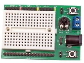
Every electronic system, even the simplest, requires a power supply. The presented board contains three stabilizers supplying voltage through pin connectors and special wires to the contact plate with pocket dimensions and 170 fields. Such boards allow you to build electrical circuits without the use of a soldering iron and tin. This pocket-sized kit will be useful for any electronics engineer to run simple analog and microprocessor circuits or test sensors.
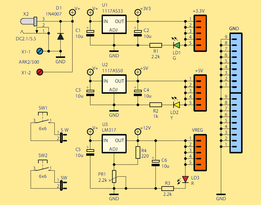
Prototype board The system should be powered from a stabilized power supply of 12-15 VDC and a current of 500 mA or more. The 1n4007 D1 diode turned on in parallel with the power supply protects the system against incorrect polarity of the input voltage.
Capacities C1 … C6 act as supply filters. The input voltage supplied from the X1 screw connector or the X2 DC2.1 / 5.5 connector goes to the three stabilizers U1-U3. The first two LD1117 provide +3.3V and +5V, and the third LM317 provides a VREG voltage ranging from 1.25V to about 10.5V on a 12V supply and approximately 13.5V at 15V.
Voltage regulation is made with the 2.2k PR1 potentiometer. For each power line, there is an indicator of voltage switching in the form of multi-colored LEDs (+3.3 V – green, +5 V – yellow, adjustable – red). Additionally, for the purposes of the circuits being built, the board has two buttons S1 and S2. Their contacts are led out to pin connectors.
Schematic Diagram Of a Prototype Board
The Prototype board is assembled on a 50x70mm board. All components used in the project are popular and easily available. The assembly of the system should begin with soldering resistors and other small-sized elements, and end with the screw connection and inserting the regulating shaft into the potentiometer.
Assembly Diagram Of The Prototype Board
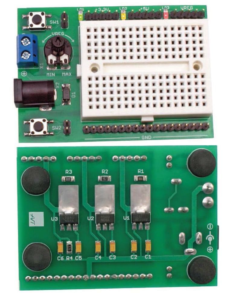
The only thing that requires a comment is to install the contact plate on the bottom, which has a double-sided adhesive tape with which it should be attached in the rectangle marked on the top side of the printed circuit.
After assembling the system, it is necessary to check whether the elements have not been soldered in the wrong direction or in the wrong places, and whether the soldering points have not been shorted. A mistake at this stage of assembly work may result in damage to the elements. Finally, 4 rubber feet can be glued to the underside of the plate to improve the mechanical stability.
![]()
FILE DOWNLOAD LINK LIST (in TXT format): LINKS-26589b.zip


