While browsing through the archives, I noticed that I downloaded the famous GTS USB programmer files from somewhere, now it is a classic programmer circuit, but it has many users, I wanted to share all the files, so they are in a corner 😉
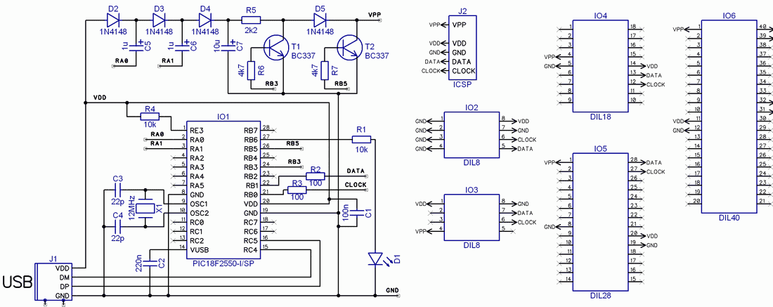
The basis of the connection is the previously mentioned PIC18F2550 processor (IO1), which controls all the functions of the programmer. While the processor is clocked by a 12 MHz crystal, this frequency is increased to 48 MHz, which is required for the USB port inside its case. It is connected to pins 15 and 16. Impedance matching resistors 22R and classic 1.5k pull-up are directly integrated into the circuit.
The higher programming voltage Vpp (approximately 13 V) is generated using a charge pump consisting of diodes D2 to D4 and capacitors C5 to C7. The charge pump is again driven directly from processor pins RA0 and RA1, which makes it possible to bypass the external oscillator that is normally required. To control the programming voltage, transistors T1 and T2 are used.

The programmed components can be placed in sockets IO2 to IO6 or programmed using the ICSP connector J2. Since I have been using the ICSP connector pin of the Presto programmer for many years and it seems to be the best, I used this format here as well.
LED D1 indicates that programming is in progress.
After connecting the programmer to the PC for the first time, it is necessary to select Install drivers from a specific location. Here, the directory with the unpacked WinPIC800 program and the Driver GTP-USB folder are selected.
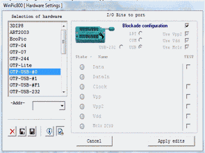
The WINPIC800 version 3.55f program is used for the programming itself and, as already mentioned, can be downloaded at the end of the article. After starting the program for the first time, you need to select the GTP-USB-#0 programmer and check the Use Vpp2 option in the upper right corner.
Setting up the WinPic800 program
This completes the installation and setup of the programmer and it is possible to start programming. There is no point in describing in detail the control of the standard WinPIC800 program here, and of course there is help if necessary.
Perhaps I would like to mention one interesting function, which is the automatic detection of the programmed processor after connecting it to the programmer (or pressing the DETECT PIC button). This feature is often not offered even by professional programmers.
Solution:
If you are mainly focused on PIC processors or even the basic EEPROM memory series, then this programmer is definitely an interesting option for you. After minor initial troubles with programming the control processor, you will get a very high-quality and professional USB programmer that can program a wide variety of circuits.
GTP USB programmer PCB, schematic, program and code files:
Şifre-Pass: 320volt.com
Published: 2010/07/10 Tags: pic18f2550 projects, programmer circuit
Regulated Buck-Boost DC DC Converter Circuit
This circuit is an example of a simple Buck-boost converter circuit. By applying the input voltage from 3v to 15v outlet will receive a fixed value that you set. Determines the minimum output voltage of the zener 10v. You can set the output with 10k pot. You can use it to get a negative voltage you apply her to.
DC DC Converter