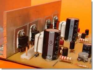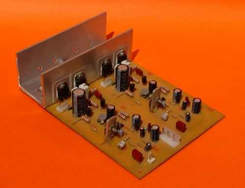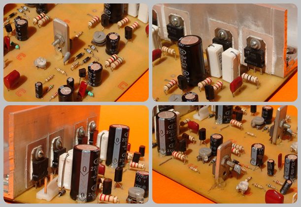
100w amp circuits 100w total output power of 50w per channel is not symmetric single source of supply for 63 volt dc supply transformer 43v ac suggested 8amp npn output transistors tip3055
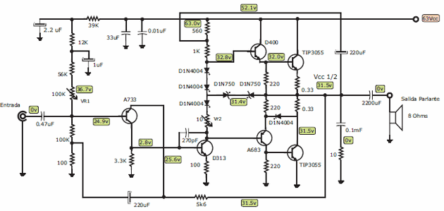
Amplifier specific areas on the circuit diagram of the given values of the voltage VR1, VR2 potentiometer can adjust to these values. You can use in the supply circuit 6A10 diode or diode bridge may be ready KBU10M specified as advice uF filter capacitor 6800uF 4700uF (80v-100v) or higher (10000uF) use a value

This configuration is known as a class AB amplifier with quasi complementary Darlington pair, and incorporates an NPN Darlington transistor pair and a consistent pair fed a retro transistor NPN and one PNP. The output transistors are NPN Similar capable of handling high power. The A683 and D400 transistors are complementary and do not need to handle high power.
TIP3055 Transistor 100W Amplifier Circuit


Source:http://videorockola.com 100W Amplifier circuit schemtic pcb files alternative link:
Şifre-Pass: 320volt.com
Published: 2010/01/22 Tags: audio amplifier circuits, transistor amplifier
TDA2004 4X20W Car Amplifier Circuit
Car amp circuit can be used for a quality used 4 tda2004 tda2004 stereo integrated amp that can provide 2 × 10 watts of power with an integrated bridge mono 20w power connection can be taken. Because it is the only source of supply voltage 12 volts from the battery supply can run with.
In addition to input 12v 2200uf 25v capacitor series addressed 2 of the coil in a relay output if you use the speaker delay circuit is more efficient.
TDA2004 Car Amplifier Circuit