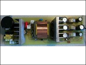
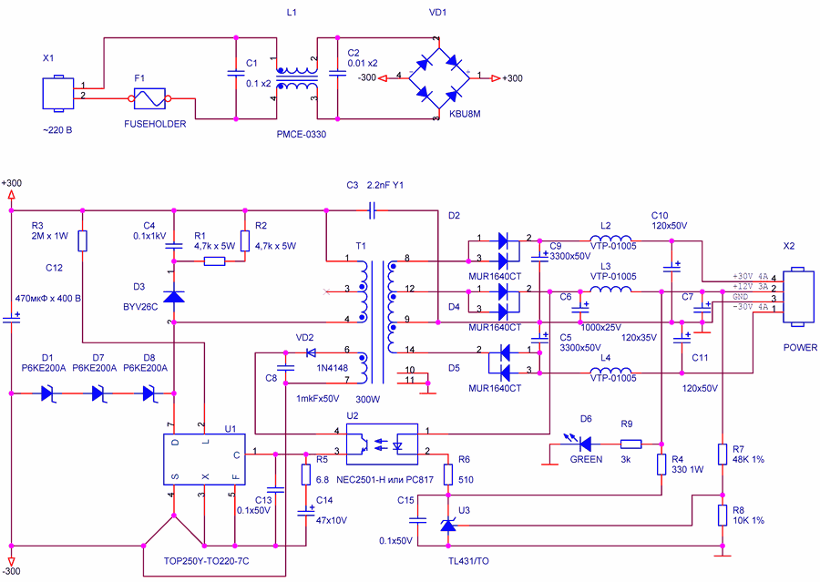
The PCB schematic files of the Smps circuit built on the TOP250Y SMPS IC are designed for the power supply of the 300w Amplifier circuit. There are 2x30v 8 amps and single 12v 3 amps voltage outputs. Transformer used in TOP250Y 300W SMPS circuit E42/21/15 air gap 0.5 mm 2000NM1 ferrite core is used.
TOP250Y SMPS Transformer Winding
The transformer pins are numbered in the diagram. The first number in the description is the starting winding.
The primary winding will be wrapped with 11 turns of 1mm wire from number 1 to number 3, then 1 turn of insulation tape winding
System supply winding from pin 6 to number 7 2 turns of 0.35mm wire. 3 turns of insulation tape wrap
2 turns of 0.1mm copper foil from number 12 to 6, 1 turn of insulation tape winding
3 turns of 0.45mm wire from number 8 to 12 (3 litz wire method to be connected in parallel) 1 turn of insulation tape winding
From 9 to 14, 5 turns of 0.45mm wire (3 pieces of litz wire to be connected in parallel) 1 turn of insulation tape winding 3 turns of insulation tape winding
The last winding (primary) will be wrapped with 11 turns of 1mm wire from number 3 to 4, followed by 3 turns of insulation tape winding.
Place and glue a 0.5mm cardboard gasket for the core gap (if there is no core gap). 0.1mm copper foil will be wrapped on the final closure insulation tape and given to the secondary chassis with a wire.
1: Practical arrangements for the replacement of discrete components: TOPSwitch provides greater reliability and smaller size than the scheme on discrete components. MOSFET- EMI. The special scheme of management power MOSFET-transistor reduces EMI.
2: Increased efficiency scheme with the transformer output to 90%: Fitted scheme “soft launch” and the current limitation reduces static losses; quick MOSFET-transistor dynamic reduces losses; MOSFET drivers consumption does not exceed 6 MW; limiting factor fill scheme minimizes loss of conductivity.
TOP250Y Switch Mode Power Supply Project

3: Simplification of development: simply built into most schemes; combined scheme controller and power MOSFET-transistor in the hull TO-220; all service functions are set by one external capacitor.
4: The high degree of protection: automatic restart and cyclic protection from overloading; built thermal protection.
5: Flexibility and multifunctionality: implements the functions of lowering the DC-DC converter
converter, power factor corrector; easily consistent with optical and transformer feedback devices.
Source: pyclan.com SMPS TOP250Y 300W schematic pcb alternative link:


Guitar Studio 400W Power Amplifier Circuit PCB
The administration, indicating and switching located on the front and back panels. For each of the entrances there is a regulator of the amplifier input to establish the necessary sensitivity. STEREO MONO. Amplifier can be operated in two modes – STEREO and MONO. In mono amplifier inputs are connected in parallel, which allows free entry to use the remainder as a linear way for further increases in the number of working in parallel amplifiers. – . Stereo-mono switch is located on the rear panel. 220v 250v At the rear panel also located the nest entrance, the network fuse, the output terminals, the switch-voltage switch 220/250 V and damping factor. The switch allows you to change the damping factor damping acoustic systems and consequently the nature of their sound