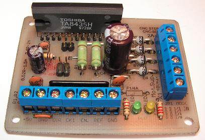
TA8435 motor control based on integrated circuits in 1.5 (2 max) can be controlled stepper motors, a lot of these values robotics, CNC, etc.. adequate for the project authors have used for milling machine motor driver board schematics and PCB drawings TA8435 eagle drawing files have been prepared by the source ..
TA8435 Motor current 1.5 A 2.5 A (PEAK)
Vcc 5V logic supply (5.5 V max)
Motor power supply Vm 24V (40V max)
Full step, half, quarter and eighth digits operation
| Label | Function | Description |
| X1-1 | +24 V | |
| X1-2 | GND | Mass input power engine it will continue. |
| X1-3, 4-X1 | A1, A2 | A connector of the stepper motor windings. |
| 5-X1, X1-6 | B1, B2 | Connector B stepper motor windings. |
| X2-1 | +5 V | Input power Vcc = 5V logic circuit.. |
| X2-2 | GND | Entry system logic supply ground. |
| X2-3 | DIR | Input direction |
| X2-4 | ADIM | Input step |
| X2-5 | ENABLE | Input control signals energizing the motor windings, L = enabled, H = off. |
| X2-6 | REF IN | Motor current control input L = 60%, H = 100%, the signal can be used to reduce the current when the motor is stopped. |
| X2-7 | GND | Input weight control signals |
TA8435H Bipolar Step Motor Driver
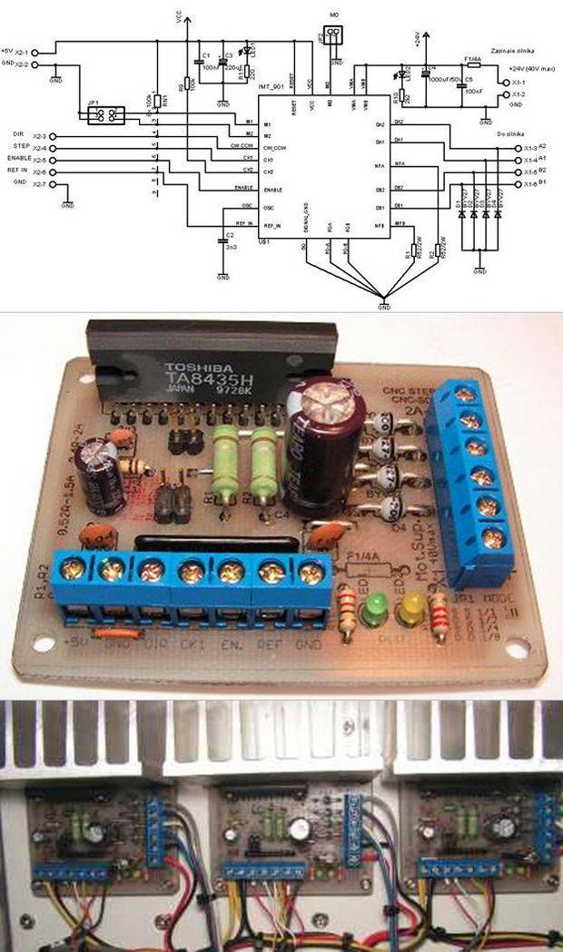
1.5A (max. 2A) motor driver based on TA8435H (IMT901) There is a description of the motor controller currently used in my milling machine. It is a driver based on the TA8435H IC (IMT901 equivalent). The controller allows you to control stepper motors up to 2A with up to 1/8 step division. This system is essentially a complete controller, requiring only a few external elements to be connected.
The structure of the controller practically does not differ from the implementation offered by the system manufacturer. The controller has inputs for step (STEP), direction (DIR), motor power on (ENABLE), and current control input (REF, 100%/60%). The controller is designed to control two phase bipolar stepper motors (4 leads). It can also be controlled by a six-pin unipolar motor.
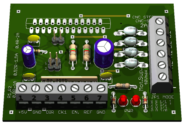
Description of controller connectors:
Assignment in diagram Function Description
X1-1 +24V Irregular +24V power supply input for motor. The system can be supplied with a voltage between 18-36V, but the use of voltages close to the maximum is not recommended due to the possibility of damaging the system. Exceeding the 40V voltage will cause immediate damage to the system.
X1-2 GND Motor supply ground input.
X1-3, X1-4 A1, A2 Stepper motor winding A connector.
X1-5, X1-6 B1, B2 Stepper motor winding B connector.
X2-1 +5V Logical power supply input Vcc = 5V of the system.
X2-2 GND System logic supply ground input.
X2-3 DIR Direction signal input
X2-4 STEP Step signal input
X2-5 ENABLE Motor windings power supply input, L=enable, H=disable.
X2-6 REF IN Motor current control input L=60%, H=100%, this signal can be used to reduce the current when the motor stops.
X2-7 GND Ground input for control signals
Configuring the controller to operate in 1, 1/2, 1/4, 1/8 step (JP1) mode:
Selecting the values of the resistors R1 and R2 (RNF):
Io = VREF / RNF
REF – INPUT = High, VREF = 0.8V
REF – INPUT = Low, VREF = 0.5V
If the controller is operated with a current of more than 1.5A, it would be good to use additional coolant temperature control systems to protect the TA8435 system from damage.
Motor connection: Both bipolar and unipolar two-phase motors with six terminals can be connected to the controller. In the case of a unipolar motor, we can connect it in two ways, achieving greater torque or greater motor dynamics.
Source: ottop.republika.pl TA8435H Stepper Motor Drive Circuit alternative link:


Lego Robot Project with PIC16F877 PIC Assembly
Two of the PIC16F877 microcontroller based on harsh economics Robot Barrier lego robot used a lot in part lego robot can be said also tip31, tip32 bridge motor driver with transistors have a more solid thanks to the movable clamping bodies can hold in front. Other robots could be called the robot obstacle seems simple compared to other projects in front of the robot has 2 units of metal such as antenna assembly software with source code and schema files have been prepared.
PL. Witam potrzebuję zakupić zakupu płyty sterownika silnika wg. zdjęcia załacznika 1 szt.
https://ibb.co/bMmTHS7Y
https://ibb.co/kg50hzV7
https://ibb.co/Lz0CYqw0
https://ibb.co/RG3SqJvr
https://ibb.co/DD0CdC3w
Hello, the necessary files for the production have been shared. No sales. You must do it yourself DIY