Stereo Headphone Amplifier circuits specifically designed for the construction of the headphone amp circuit but none impressed me with its parameters of the output signal, thus I went into the design of the amplifier with discrete output stage and integrated exciter output stage.
Nothing, however, is not free, so you can not always increase the output power of the amplifier, because the amplifier operates in class B and This implies that the efficiency of the amplifier is very inefficient, however, for the amplifier headphones designed for an output power of approximately 1W amply sufficient and problems. This classic wiring power amplifier with discrete transistors, although this is true only in half, because the input and driver circuits are fitted with high quality ultra a low noise amplifier type NE5534AN. Amplifier output power is approximately 1W, particularly given the end transistors in TO92, with amplifier However, the performance headphones enough.
Headphone Amplifier Schematic Diagram
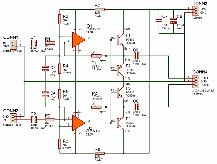
For input circuits and driver output stage I chose a high quality and fast low noise operational amplifier NE5534AN, which has extremely low signal distortion 0.005% and signal to noise ratio is better than 84 db. Because of the complementary pair of transistors T1 terminal (BC639) and T2 (BC640) operates in pure class B (no surge), the operational amplifier IC1 manage elimininovat inevitably emerging crossover distortion, use a circuit NE5534AN therefore entirely justified and recommended.
Driver and output stage is powered by the unbalanced voltage 9V to 12V, therefore, must resistive divider R3/R4 (56kΩ/R0207) to create a virtual center of supply voltage, which is applied to the noninverting input (Pin 3) of the operational amplifier IC1 (NE5534AN). This voltage is subsequently filtered by a capacitor C3 (10μF/25V). The gain of the output stage is determined by the feedback potentiometer P1 (250kΩ/PT10LV) ing out of position gain is approximately the 15th circuit output from the emitter terminal Transistor T1 (BC639) and T2 (BC640) is routed through the coupling capacitor C5 (470μF/16V) to the terminal CONN4 (JACK 3.5 ).
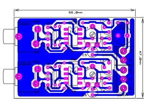
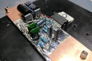
Supply voltage DC +12V are bringing to the terminal CONN3 which is then filtered by an electrolytic capacitor C8 (470μF/16V) and C7 (100nF/TK ker.) And then is routed directly to the final stage of complementary the transistors T1, T2, and through isolation resistor R7 (22Ω) to the exciter terminal degree IO1 (NE5534AN). The amplifier is placed on one side PCB with dimensions of 66x47mm. After installation of all components check headphone amplifier PCB connections for error when soldering if we did not create local faults and tin bridges. Amplifier except one resistive trimmer P1 gain adjustment does not require No additional settings. When animating only dial the trimmer P1 to the middle position, which should be equal to the circuit gain to around the 15th to the A input low-frequency signal and to output stereo headphones, turning the trimmer P1 desired gain of the output stage, so that the signal was not affected distortion due to overdriving the output stage.
NE5534AN Op-Amp Headphone Amplifier PCB Schematic files download:
FILE DOWNLOAD LINK LIST (in TXT format): LINKS-25344.zip

Active Subwoofer Amplifier Circuit TDA7294 VU Meter DC to DC Converters
Active subwoofer amp designed for use in the car cabin floor TDA7294 2SC5200 and 2SA1943 used, but the addition of an integrated output power to the output of this circuit is upgraded patlaşıl previously had different PCB drawing ; TDA7294 Power Transistor Output Power Enhancement Supplements
TDA 7294 2x38v DC symmetrical supply is working with cars for use in the TL494 PWM control integrated on the board dcdc converter circuit
12V NE5534AN Einfache Qualität Kopfhörerverstärker
Stereo-Kopfhörerverstärker-Schaltungen, die speziell für den Aufbau der Kopfhörer-Verstärkerschaltung entwickelt wurden, aber keine beeindruckten mich mit seinen Parametern des Ausgangssignals, so ging ich in das Design des Verstärkers mit diskreter Ausgangsstufe und integrierter Erreger-Ausgangsstufe.
Nichts ist jedoch nicht frei, so dass Sie nicht immer die Ausgangsleistung des Verstärkers erhöhen können, da der Verstärker in Klasse B betrieben wird. Dies bedeutet, dass der Wirkungsgrad des Verstärkers für die für einen Verstärker konzipierten Kopfhörer jedoch sehr ineffizient ist Ausgangsleistung von ca. 1W reichlich ausreichend und Probleme. Diese klassische Leitungs-Endstufe mit diskreten Transistoren, obwohl dies nur in der Hälfte der Fälle gilt, weil die Eingangs- und Treiberschaltungen mit einem hochwertigen Ultra-Low-Noise-Verstärker vom Typ NE5534AN bestückt sind. Verstärker Ausgangsleistung beträgt ca. 1W, vor allem angesichts der End-Transistoren in TO92, mit Verstärker, aber die Leistung Kopfhörer genug.
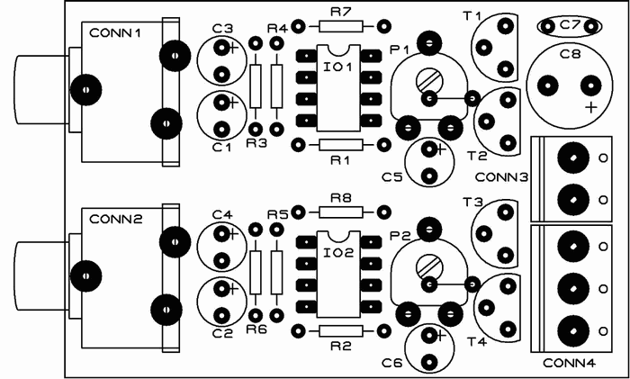
Looking at the pcb for this project, I believe you have the labels for T3 and T4 reversed. Also, I cannot see where the 12v supply links to T4c and R8.
Regards
Bill