So far I have not seen such a circuit in a web environment could work in mass production programming section has been removed by the original photos used only copying part of an integrated control pic16c64 asm lib, etc. scr. There are resource files (.lzh extension, you can open files with WinRAR) with one source can be copied pic 8 18 volt dc supply voltage is regulated with 78xx series
Example of a project that will be different from the pic asm source code and hardware can be copied guess changing


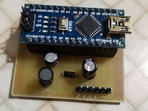
The two AC power adapter from the regulator output from +5 V and +12 ~ 14V terminals are available. Thus, AC power adapter is needed about + 16V (using the AC adapter is rated at +12 V is used, try to measure the actual output was more than +16 V out). The capacity is about 500mA. No batteries are used in the experiment, we can note that the capacity problem.
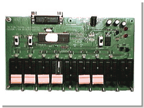
This will be the master one PIC16C84 (or F84) will be targeted to a maximum total of eight programs PIC16C84 (or F84) was used to control the circuit diagram and writer writer had to copy those programs PIC16C64 . (Photo above is what you manufacture printed circuit boards produced by Mr) In addition to copy a simple comparison of the master and the target (compared to when we copy), and also give protection to the target after the copy of the program. PC The device is no need to connect with PC, operating independently, it is no use to anyone.
Red and green LED is not a one has three legs. 3 Single red, single green, red to green and the simultaneous emission red, green and orange colors .
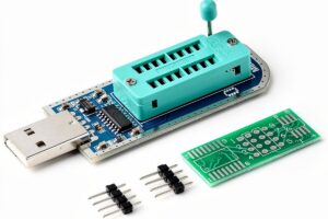
PIC16F84 Multiple Programming Circuit schematic pic assemby source code files :
PIC16F84 LED Display Frequency Counter Circuit
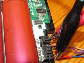
LED 6 digit display for rig frequency counter -Just as it may seem at frequency display of rig, and produced a dot LED-PD4435 counter, and make use of this in the future, and that the “sold out, there is no plan of the re-arrival” and. To give up this, I made a 6-digit display using the 7-segment LED.
7 segment LED 6-digit precision TCXO 12.8MHz (1ppm), PIC16F84 with 1MHz ~ 300MHz (400MHz) IF offset frequency counter. TD7104P (Prescaler ÷ 8, ÷ 1) +2 SC1906 later in the preamp, PIC 16F84A-P20 count, LED display TC4511 drivers. Left; 144.90MHz handy 200mW transmission. ANT of the counter, lead 5cm yellow alignment there. And Central; 7,649.1 kHz SG signal. Minimum digit 100Hz. Zero blank function put, unnatural 0 of top disappear. And right; at 33.1688MHz, it is not. 433.17MHz handy 200mW transmission.