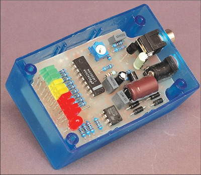
We usually see the LM3914 integrated in vu-meter circuits. In this application, it is not different. In addition to the control layer designed to monitor the water tank level with LEDs, the resistor group is connected via the tos socket for level detection.
Tank Water Level Indicator
Water tanks are undoubtedly a good idea. But once installed, how can you determine how full (or how empty!) your tank really is?
There are several traditional methods for finding the water level, among them: (1) lightening the side of the tank until the sound suddenly changes; (2) on a hot day, feeling the tank down for a change in temperature; (3) pouring boiling water near the tank and looking for the condensation line; and (4) removing the tank cover and dipping a dipstick.
The first two methods are notoriously unreliable, while the last two have their own problems. Only the last one is true. But who wants to climb over a tank when you want to find out how much water is in each tank?
That’s where this simple device comes into play. It uses an array of ten colored LEDs arranged in a bar graph display to clearly show how the water supply is being held. The more lights on, the higher the water in the tank.
The LEDs are arranged in the familiar “traffic light” colors of green, yellow and red to instantly show relative levels at a glance (green is good, yellow is not so good and red is bad!) as well as relative levels at a glance.
Another red LED illuminates when the tank level drops below a critical threshold.
There are no fancy microcontrollers or digital displays used in this project. Instead, it uses only the LM3914 NE555 and a handful of passive components to keep the cost as low as possible.
It can be used in a traditional metal tank or in one of the newer thin plastic jobs. As long as you have access from top to bottom inside the tank, this circuit will work.
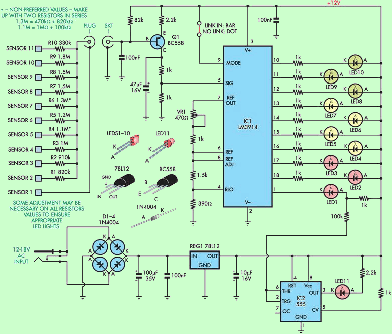
Water Level measurement circuit diagram
Water Tank Level LED Indicator

Circuit description
This design is based on the LM3914 linear LED dot/bar display driver (IC1). Pin 9 of the LM3914 is connected so that the display will be in bar graph mode and the height of the LED column will indicate the level of water in the tank.
However (and this is one of the minor tweaks we’ve made), this pin can be easily isolated, saving power by switching the screen to point type. if you’re using it from a battery source, every milliamp counts!
The full scale range of the bar depends on the voltage at pin 6. This voltage can vary from about 1.61V to 2.36V using the VR1. After accounting for the voltage across the 390Ω resistor on pin 4, this gives a full range switchable between about 1.1V (VR1 set to 0W) and 2V (VR1 set to 470Ω).
By the way, if you’re wondering where the above voltages are coming from, keep in mind that IC1 has an internal voltage reference of 1.25V between pins 7 and 8. This allows us to calculate the current with VR1 and 1kΩ series. Since the same current flows through the array of 1.5kΩ and 390Ω resistors, we can calculate the voltages at pins 6 and 4.
Besides adjusting the full-scale range of the bargraph, the VR1 also adjusts the brightness of the LEDs 1-10 in a small range. However, this is only a secondary effect – it is the full-scale range that matters here.
Source: http://www.siliconchip.com.au/cms/A_109005/article.html
Water Tank Level Indicator Circuit PCB schematic alternative link:


Subwoofer Control Circuit
Multipurpose a control circuit low pass, high pass, Filter sections 30 .200 kHz Parametric Equaliser solid frequency, level, boost controls have also disabled SS SY-4089 (Solid State Relay) was isolated by the amp from the mains supply cuts electronic key Node there