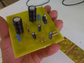
TDA2052, AB class (+, – 25V) 60W working with symmetrical feeding (Music) output power amplifier is capable of producing. Low distortion and due to the AB class for Hi-Fi system may be preferred. Integrated the MUTE / STAND-BY feature can be turned off and the output can be controlled by digital circuits. In Integrated over-temperature protection and output short circuit protection are available.
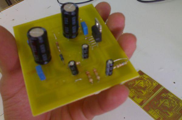
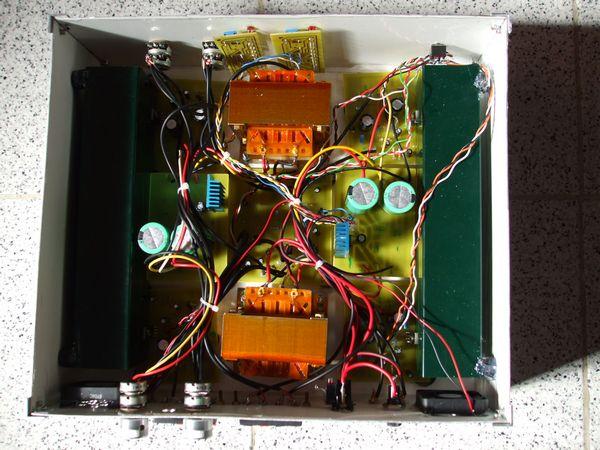
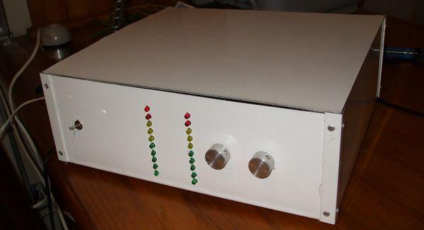
TDA2052 Amplifier Circuit Test
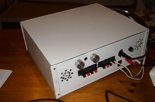
Waist voltage: +, – 25V
Maximum output current: 6 A
Operating temperature: 0 to 70 C
Power consumption: 30W
Maximum output power: 60W music power (4 ohms-32W RMS for 1% distortion, 8 ohms-18W RMS)
Output load: 8 ohm or 4 ohm
Input signal voltage: 1mV (minimum), 1V (pp) (maximum)
Input signal current: 1mA
Standby current: 3mA
Half of the members of the task are as follows;
R1 – Input Impedance
R2, R3 – Gain (32dB)
R4 – in Mute input impedance
R5 – Standby pass-time
R8 – Frequency balancing. (Out of the dangerous oscillation is prevented from entering)
R9, R10 – Discharge resistors
C1 – Input coupling capacitor
C3 – Feedback coupling capacitor
C4 – Standby pass-time
C5 – Frequency compensation
C6, C7 – Supply voltage balancing capacitors
C9, C10 – Supply voltage filter capacitor
TDA2052 4X60Watt Amplifier Project pcb schematic :
Şifre-Pass: 320volt.com
Published: 2008/04/07 Tags: audio amplifier circuits, ic amplifier
Computer Controlled Smart Home Project with PIC16F873
Smart home automation control project your computer on the control program and PIC16F873 on board with the circuit bulb lights on the severity of your air conditioner temperature or any engine speed ayarlayabilirsiniz.sens you and help through a program within your home, temperature, pressure, light settings, such as physical values that lets you control a system a completely free and full project .. 🙂
Hi! Thanks for uploading this project. I’m trying to build the same, without any succes. I measure the -Vs on the output (pin1).
Do you use the same circuit from the datasheet example? It’s not working for me. Maybe the IC is not working properly. Could you suggest any source to buy from?
Thanks!