The amplifier uses a hybrid two-channel IC STK4241-II manufactured by SANYO. Immediately, it is worth noting that the pinout of the STK4241 is compatible with such chips as the STK4201V-series (THD = 0.08%) and the STK4141-series (THD = 0.02%). In the archive for download you will find 5 technical descriptions (DATASHEET) on STK4201, STK4211, STK4221, STK4231 and STK4241.
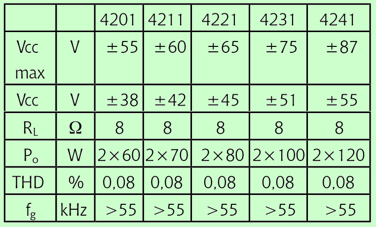
According to the Datasheet on STK4241-II, the recommended supply voltage is 2 x 54V DC, the load resistance is 8 ohms, the input impedance is 55 kΩ, the output power is 120 + 120 watts. We give the technical characteristics of the amplifier (data taken from the datasheet)
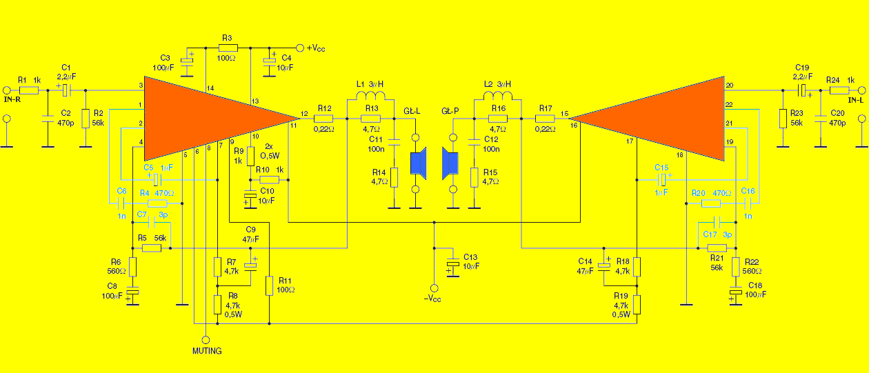
Schematic diagram STK4241

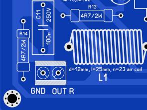
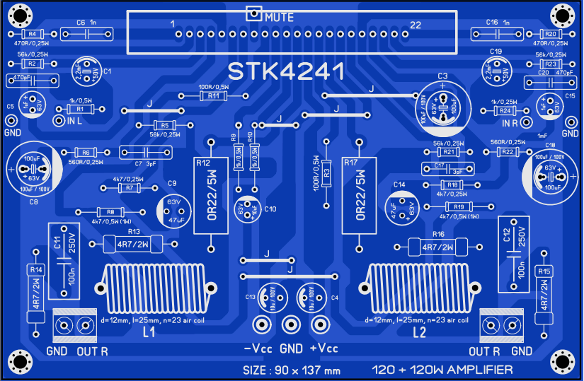
L1, L2 – 3mH – diameter 12 mm, 22 turns, 1 mm wire 2 Pin connector with bolt clip for connecting output wires For powering the amplifier, the datasheet recommends a 500-watt transformer with secondary voltages of 40 – 0 – 40 Volts AC


Part list
Resistors:
R1 R24 – 1k / 025W – 2 pcs.
R2 R5 R21 R23 – 56k / 0.25W – 4 pcs.
R3 R11 – 100R / 0.5W – 2 pcs.
R4 R20 – 470R / 025W – 2 pcs.
R6 R22 – 560R / 025W – 2 pcs.
R7 R18 – 4k7 / 025W – 2 pcs.
R8 R19 – 4k7 / 05W – 2 pcs.
R9 R10 – 1k / 05W – 2 pcs.
R12 R17 – 0R22 / 5W – 2 pcs.
R13 R14 R15 R16 – 4R7 / 2W – 4 pcs.
Capacitors:
C1 C19 – 22mF / 50V electrolyte
C2 C20 – 470pF / 63V
C3 C8 C18 – 100mF / 63V electrolyte
C4 C10 C13 – 10mF / 63V (100V) electrolyte
C5 C15 – 1mF / 63V electrolyte
C6 C16 – 1n / 100V
C7 C17 – 3pF ceramics
C9 C14 – 47mF / 63V electrolyte
C11 C12 – 100n / 250V
FILE DOWNLOAD LINK LIST (in TXT format): LINKS-26106.zip
Publication date: 2019/06/13 Tags: audio amplifier circuits, ic amplifier
LTC3652 Solar battery charger LiFePo4
LTC3652 Solar battery charger LiFePo4
The charger presented in the article is intended for charging the battery pack – LiFePO4 2S 1.8Ah with electricity from a photovoltaic cell. The charger is based on a LTC3652HV integrated circuit which is a universal battery charger controller, adapted to be powered from a PV solar panel. Recommendations: the charger is worth taking with you on trips to the terrain, camping, etc.
As mentioned in the introduction, the charger is basically an application of a specialized integrated circuit LT3652HV, which has a built-in PV peak power peak tracking algorithm similar to MPPT.
Block diagram of the LT3652HV system is shown in Figure 2. The system includes a reduction converter with a wide input voltage range and a maximum load current of 2 A. The system is designed for charging batteries made in the most commonly used technologies: AGM, LiPo, LiFePo using the CV / CC algorithm, enabling the charging of packages with a voltage of up to 18 V. It has a built-in thermal protection circuit for the battery, a charging timer and circuits for signaling operating states.
Schematic Diagram of the LiFePo4 Charger
STK4241 STK4201 STK4221 STK4211 STK4231 Circuit d’amplification
L’amplificateur utilise un IC hybride à deux canaux STK4241-II fabriqué par SANYO. Immédiatement, il convient de noter que le brochage du STK4241 est compatible avec des puces telles que la série STK4201V (THD = 0,08%) et la série STK4141 (THD = 0,02%). Dans l’archive à télécharger, vous trouverez 5 descriptions techniques (FICHE TECHNIQUE) sur STK4201, STK4211, STK4221, STK4231 et STK4241.
Selon la fiche technique du STK4241-II, la tension d’alimentation recommandée est de 2 x 54 V CC, la résistance de charge est de 8 ohms, l’impédance d’entrée est de 55 kΩ, la puissance de sortie est de 120 + 120 watts. Nous donnons les caractéristiques techniques de l’amplificateur (données extraites de la fiche technique)
Diagramme schématique STK4241
where can i buy the pcb for STK 4241II
With gerber files you can order PCBs from any manufacturer
okay