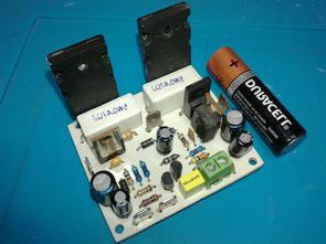
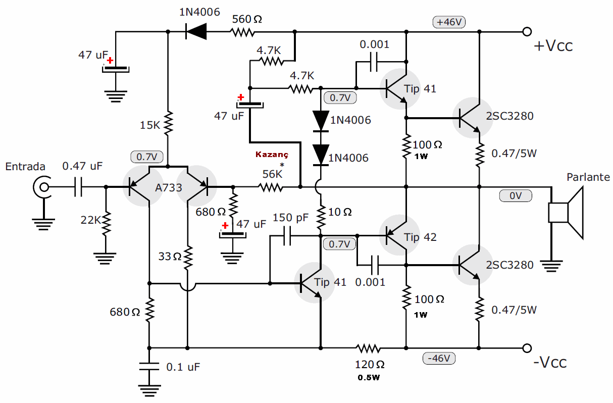
100W Amplifier circuit provides high power with less material. Output transistors 2 2SC5200 NPN transistors. PNP transistor is not used for output in this amp design. The operating voltage of the 100W Amplifier circuit is 2X46V DC. If you want to operate at higher voltage (max. 2X56V DC), you should use 2SC3858 or similar power transistors instead of 2SC5200.
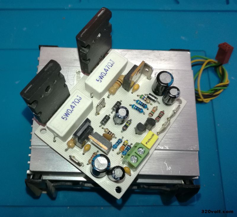
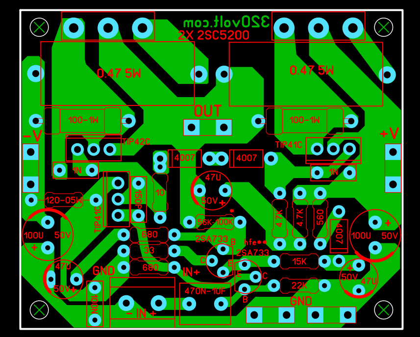
The 100K resistor connected to the base of the 2SA733 transistor from the amplifier output adjusts the gain of the amp. You can use it between 56K….100K. The author added a passive tone control circuit to the audio input of the same circuit and used 100K gain resistance. 100W Amplifier PCB printed circuit design was prepared with Sprint layout 6 PCB dimensions are 60x50mm.
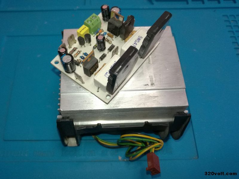
Other details such as transistor and power supply are given in the 1/4W test video for those who do not have power values on the resistors with high power. PCB printed circuit drawings of 2SC5200 RMS 100W Amplifier circuit prepared with Sprint layout 6 PCB dimensions 60x50mm
100W Amp Circuit Diagram
FILE DOWNLOAD LINK LIST (in TXT format or file): 27968a.rar pass: 320volt.com
Source: videorockola.com
Publication date: 2021/09/19 Tags: audio amplifier circuits, transistor amplifier
Pls give me 5.1 remote control circuit pdf
Have not tried it yet, your projects are amazing!
So cool projects