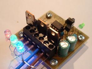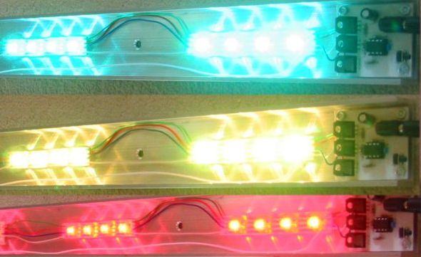
RGB LED driver circuit can be controlled with PIC12F629 pic12f675 As an alternative, can be used PIC12F683 PIC GP0, GP1, GP2 STP36NF06 in output MOSFETs are driven by PWM technique internal oscillator of the microcontroller is used instead of an external crystal. RGB Led source application software prepared by assembly hex asm code, schematics, PCB drawings there.

Code to fade between colours is completely rewritten to use variable rate of change so that all three LEDs arrive at their new levels simultaneously. This code will run on 12F629 / 12F675 and 12F683. Select the desired processor from the Configure – Select Device menu option in MPLAB IDE, then use the Project – Quickbuild option to create the HEX output file.
Look for errors during assembly. In particular errors in the SequenceData.inc file that indicate either a missing comma in the data, or more data than the chosen PIC has available program memory. Be carefull to enter the data in the SequenceData.inc file correctly. The program is only smart enough to work out where your sequences start and finish if you enter it in the correct format. Errors in the data may cause the code to crash.
All timings are based on the internal 4Mhz PIC oscillator. The OSCCAL value is read from program memory at 0x3FF and written to the OSCAL register. This value must be present and correct.

Source: picprojects.org.uk alternative link:
Şifre-Pass: 320volt.com
Published: 2011/08/27 Tags: led projects, microchip projects, microcontroller projects, pwm circuits
Sequential LED Applications MSP430 Launchpad
In this work, known as sequential LED or LEDs LEDs and resistors established walking circuits respectively’ll tell you. Each combustion mode and video codes are below. Feridun GÖKÇEÖZ also our friend “MSP430 Uyg.3 – Sequential LED Application” I would suggest that you review the article.