555 timer IC is an integrated circuit used in a variety of timer, pulse generation circuit, and oscillator circuit applications. The 555 can be used to provide time delays, as an oscillator, and as a flip flop element.
Timing has an integrated circuit made ??with N555 hundreds of years in the market all the electronic equipment in the shop a popular integrated See here for a detailed knowledge of Turkish. Circuit as musical notes can give a voice to the series resistance values ??button is pressed, left to right according to the RE,…
I do not know who has prepared the book, but a very simple circuit diagram found on the internet’s opamps circuits, transistor circuits, integrated circuits, etc. 555. There is also a variety of information Data Book was the first book in style but all content from different sites have been compiled into a single PDF…
A simple alarm circuit but Mr. deterrent siren voice of the author would not last 🙂 circuits infrared transmitter and as a receiver consists of two parts transmitter circuit also 555 integrated with a controlled IR LEDs have a (tv remote control used in) LED signals sent by other circuits as well TSOP (38kHz or…
When triggered by a button integrated in the circuit relay 555 timer is energized and immediately set is full when you leave the ignition again. working time is determined by the 220k potentiometer and capacitor C1. Receiving single trigger for the start of timing is sufficient. Trigger Circuit Schematic Diagram
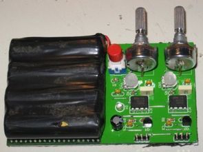
Servo motor test circuit the same simple structure made of circuit ne555 timer IC 2 piece disabled based on servo motor can be used in different applications depending on the situation or the test writer to run the circuit 4 x 1.2 v rechargeable batteries, used by linking instead of the 5v adapter serial Servo…
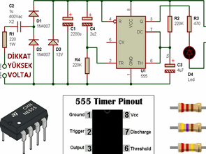
Made with 555 timer integrated timer circuit is supplied from the power supply transformerless transformerless voltage to the circuit drawing too much current is available with leveling . However, where there is a high danger of trying to be very careful with this type of connection is required. R1 , C1, C2, D1, D2 and…
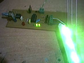
Circuit ne555 and 74393 circuits based on single piece is tested with the rgb led Strip Ribbon if you want to use more than the output of the led with the necessary tubing circuit transistors used in 12v 74393 works with the integration of LEDs with 100 k potentiometer connected to 555 speed can be…
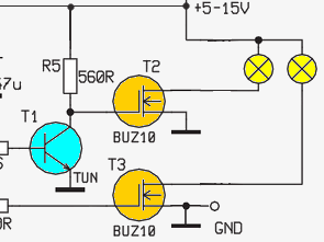
you can see in the circuit diagram circuit, which runs between 5- 15V two 70 -watt lamp brightness increased or decreased . 1X1 and 1X2 circuit power supply input terminals of the ends and between 5- 15V input must be provided. 2X1 and 2X2 ends are the ends of the lamps to be connected .…
In the diagram you can see the circuit, which integrates popular NE555 is used. This integrated using the PWM of a DC motor and / or a lamp is driven by PWM pulses. Together with the engine, the purpose of the lamp using the N-channel MOSFET is from obtaining a strong output. Of course it…
Led flash circuit 180 leds optionally control solid canceled and the only lighting available in LEDs for current limiting made printed circuit board layout beautiful circuit has two positions, if desired NE555 floor can be adjusted with the LEDs flashing (together) are provided or LM358 times the audio input flashing making offers. Pcb circuit layout…