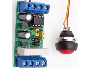
ATtiny25 Programmable Timer To describe the operation of the device, we will use an example – control of the electromagnetic bolt mounted in the wicket. In the simplest version we require that the push button attaches the bolt electromagnet for a certain length of time, sufficient to reach the gate. Then, the solenoid should be turned off. When analyzing the situation more precisely, we find that the solenoid does not have to be turned on when it reaches the gate, and only when it reaches the gate. So we teach the device the following sequence: output disabled for 10 seconds, then turned on for 3 seconds, then temporarily off and end learning. From now on, after pressing the button, the device will perform exactly the same sequence that will trigger the lock after 10 seconds, once we reach the gate, stay drawn for 3 seconds and finally be released. ATtiny25
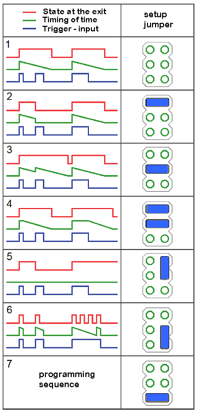
Diagrams showing action each mode and corresponding to it jumper setting

Programmable Timer Mode 1: Simple timer. As soon as the button is pressed, it starts playing the sequence until it is finished. During playback does not respond to the button.
Programmable Timer Mode 2: Interrupt timer. As in the first mode, but pressing the button during playback will immediately end the playback. As a result, the sequence can be aborted at any time by pressing the button again.
Programmable Timer Mode 3: Timer with restart. As in the first mode, but pressing the button during playback starts playing again.
Programmable Timer mode 4: End time switch. At the moment of pressing the button, it sets the first state of the sequence at the output and remains as long as the button is pressed. When the button is released, it starts playing the sequence, at that time it does not respond to the button.
Programmable Timer mode 5: Bistable switch. Each subsequent pressing of the button changes the state of the output to the opposite. The programmed sequence is not executed.
Programmable Timer 6: loop play. At the time when the button is pressed, a programmed loop sequence is output. Releasing the button immediately completes the sequence playback.
Programmable Timer 7: Sequence programming.

Programmable Timer Circuit Schematic ATtiny25
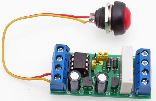
The schematic diagram Programmable Timer of the device is shown in Figure 2, and the assembly in Figure 3. The microcontroller application is straightforward and requires no discussion, just like assembly. All “power” of the programmable switch is included
FILE DOWNLOAD LINK LIST (in TXT format): LINKS-25818.zip
Published: 2017/10/01 Tags: avr project, microcontroller projects

Programmierbarer Timer-Schaltkreis ATtiny25
ATtiny25 Programmierbarer Timer Um den Betrieb des Geräts zu beschreiben, verwenden wir ein Beispiel – Steuerung des elektromagnetischen Riegels, der in dem Wicket montiert ist. In der einfachsten Version benötigen wir, dass der Druckknopf den Riegelelektromagneten für eine bestimmte Zeit befestigt, die ausreicht, um das Tor zu erreichen. Dann sollte der Elektromagnet ausgeschaltet werden. Wenn wir die Situation genauer analysieren, stellen wir fest, dass das Solenoid nicht eingeschaltet werden muss, wenn es das Tor erreicht, und nur wenn es das Tor erreicht. Also bringen wir dem Gerät die folgende Sequenz bei: Ausgang für 10 Sekunden deaktiviert, dann für 3 Sekunden eingeschaltet, dann vorübergehend ausgeschaltet und das Lernen beendet. Von nun an, nach dem Drücken des Knopfes, wird das Gerät genau die selbe Sequenz ausführen, die das Schloss nach 10 Sekunden auslösen wird, sobald wir das Tor erreichen, bleibt für 3 Sekunden gezeichnet und wird schließlich freigegeben. ATtiny25