How the Security Circuit Works: The B and D ports of the pic16f877 used in the circuit are selected as inputs. Of these, 8 doors, windows and etc. with port B. Logic 1 or 0 status from places is evaluated. On the D port, the predetermined password required for the system to work or to be stopped is entered.
A and C ports are selected as outputs. Status leds and alarm circuit are driven with A port. A 7-segment LED display is used as an indicator showing where the warning coming from port C and port B is coming from.
The 1st led of the A port is used to determine whether it is 1 or 0 instead of the alarm circuit, the 2nd led enter the password, the warning led is 3. led is password correct led and the system becomes active 4 seconds after this led is lit. The 4th led lights up when we enter the password and stop the system.
Schema pcb and assembly code files Thanks to those who contributed
Circuit diagram
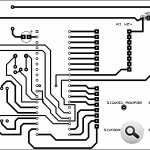
Security System Schematic PCB
Central Security System with pic16f877 pic assembly source code
Şifre-Pass: 320volt.com
Published: 2008/11/17 Tags: microchip projects, microcontroller projects, pic16f877 projects


Analog LED Clock Circuit AT89C2051P
301 LED Analog Clock Project Schema Files of PCB and C51 Compiler Source Code has been prepared by the C-in hex
The clock circuit is made of 301 LEDs with a diameter of 3mm forming fi = dial (the most one LED is in the middle), and 12 LEDs Stroke hours. The LEDs are arranged in seven zones. The three most outer rings comprise 60 LEDs each, and four inner circles each comprise 30 LEDs each. It was dictated by the size of the clock, which size is similar to the size of a CD, which shows the photograph above. Just the size of the clock made the four inner circles not accommodate the full amount of 60 LEDs. However, I used a trick here: namely, control LEDs is done in such a way that the diodes in the inner circles light up alternately with the movement direction. The final result is more than satisfactory.
Analog LED Clock Project