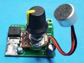
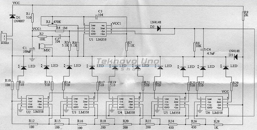
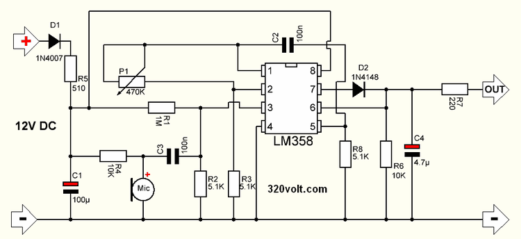
The microphone vu meter circuit was normally a classic design with 10, I just rearranged it as a single channel strip led vu meter by using the microphone preamp stage and increasing the output power with 50N06 mosfet IRFZ44, IRF3205 and similar N-channel mosfets can be used instead of 50N06 mosfets used in the LM358 opamp output.
Depending on the type of led strip, 5…10 meters of led can be connected. More powerful mosfets and heatsinks are required.
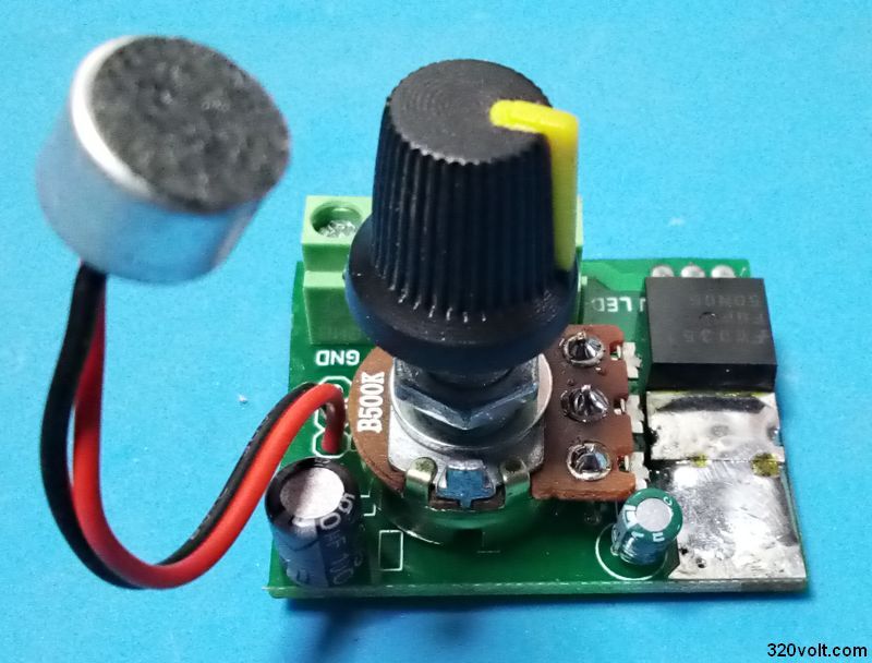
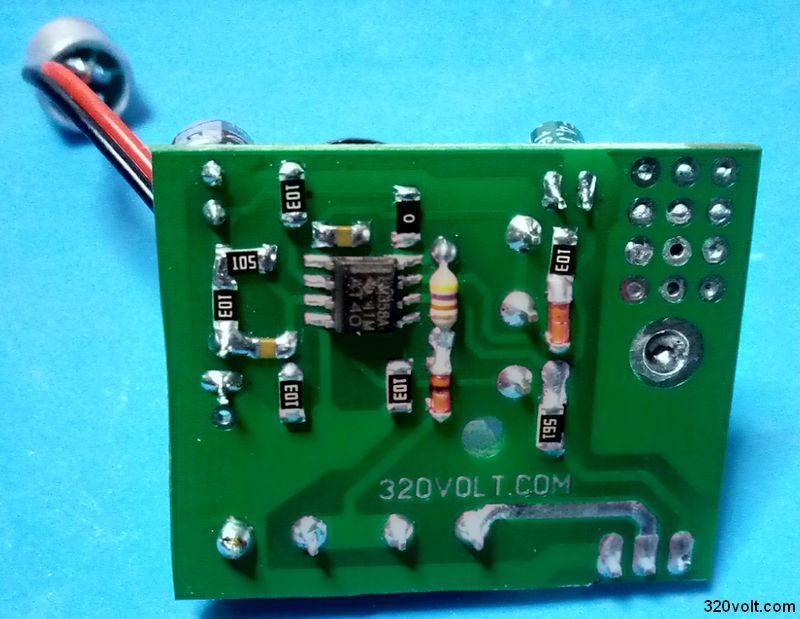
In order to keep the size small, I used a mix of SMD and DIP materials in the PCB design, actually the PCB size would have been smaller, but I didn’t bother more because the large potentiation was easy to adjust. Could have been smaller if I used trimpot.
Note: Since I don’t have a 5.1K resistor in my 1206 case for SMD resistors and capacitors, I made 2 10K parallel connections instead. I connected 2 560-ohms in parallel in a 220-ohm resistor, the closest value was 560-ohm.
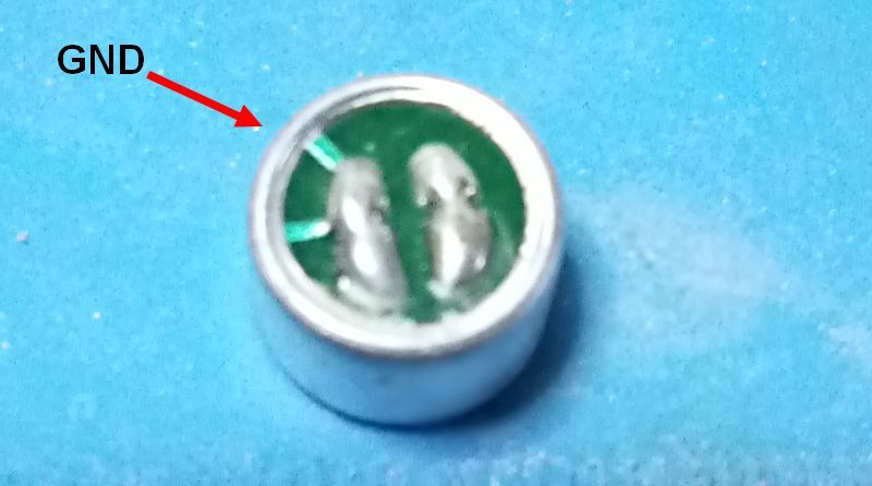
If the capacitive electret microphone that you will use in the microphone vu meter circuit is wireless, be careful to connect the chassis correctly.
The PCB dimensions of the microphone vu meter circuit are 36.4mm X 30.6mm drawing single layer. PCB drawing made with Sprint layout 6
Microphone Vu Meter Test Video
Microphone Vumeter Circuit Diagram
FILE DOWNLOAD LINK LIST (in TXT format or file): 27669a.rar pass: 320volt.com
Published: 2021/09/20 Tags: analog circuits projects