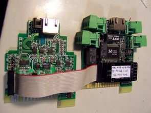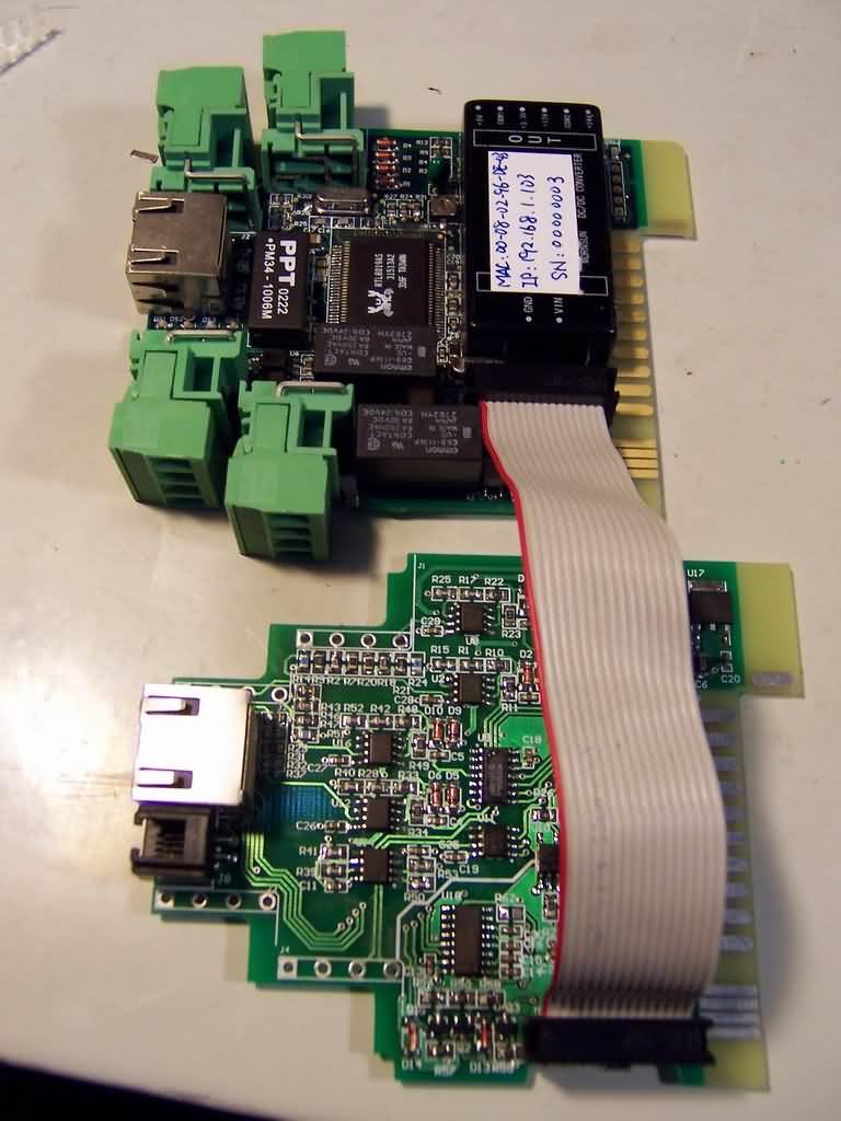
Ethernet Data Acquisition and Control System Based on LPC2132 This document describes Ethernet Data Acquisition and Control System in detail, including features, system architecture, hardware architecture and software characteristics. Future proposals will be introduced later. Schematics will also be added in the APPENDIX.
Nowadays, data acquisition and control equipment such as DDC, data acquisition adapter or PLC are widely used in industrial field. Most of these equipments work alone without networking feature. Some of them such as CAN-bus, CC-link, RS-485 and even RS-232 can be connected to a PC via field bus. The system may encounter performance bottleneck in case of needing to exchange lots of data between terminals and server. System topologies limited by physical features of such classical field bus technologies are not suitable for large-scale project.
Some solutions have come out with internet connection feature. There are many gateways and routers in the market that can connect traditional field bus to internet. However, traditional field bus specifications rarely define the communication protocol at software layer. Vendors have to customize the protocol for specific customers. Then, compatibility issues arise.

Why not bring existing standards like Ethernet to the field control area? Cost can be a sensitive reason. With the development of microcontrollers and software technologies, Ethernet will be much more popular than it was 5 years ago. Especially with the decreasing price of 32-bit processors, Ethernet can be easily incorporated into low-cost embedded systems. By this, I mean that it is possible to implement Ethernet interface in a system that costs no more than 20 USD.
Philips LPC213x microcontrollers are good solutions for such applications. Its high PPR (Performance/Price Ratio) provides Ethernet capability even when your system cost is limited to 20 USD. With the high-performance ARM7TDMI core, complex protocol stacks like TCP/IP can be easily processed. The remaining computational capacity can be used for signal processing and intelligence control algorithms.
FEATURES
This data acquisition and control system can provide the following features.
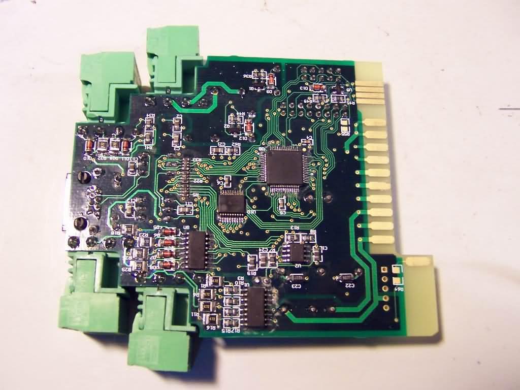
On the main board:
10 Mbps Ethernet connection feature with RJ45 UTP interface
8 channels of separate switching signal input
2 channels of relay output with 5A(max) current load at 250V
2 channels of counter input with input frequency up to 100 kHz.
I2C interface for communication with other boards on the rear panel
Built-in temperature sensor monitoring working environment
Built-in isolation power supply improves EMC
All input/output channels are isolated with microcontroller, providing higher reliability for industrial field applications.
Color LED indicates working status.
Button-free operation, working parameters can be set on the server.
Plug-in adapter installed ISP feature, enabling in-system programming. You can easily upgrade the firmware.
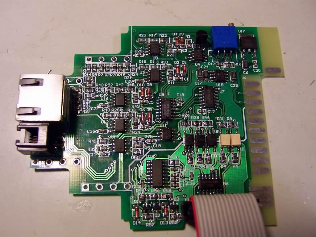
With plug-in adapter:
4 channels analog signal input, 4~20mA current loop inputs or 0~10V voltage inputs, free combination (but total channel shall not exceed 4).
2 channels analog signal output, each with maximum 20mA output current and 0~10V voltage.
2-way RS232 port in one RJ45 jacket, another configuration is 1-way RS232 and 1-way RS485 port.
ISP control circuit
Isolated SPI interface to isolate analog signal channels with controller.


Şifre-Pass: 320volt.com
Published: 2010/05/23 Tags: arm project, microcontroller projects
Keil mcb2130 lpc2138 proton precession magnetometer
The highly true parallel Cation Precession Meter is designed around a Keil MCB2130 assessment surface. The on-board LPC2138 microcontroller samples a attractive facility and implements an germinal rule to canvass the communication. This method results in determination advisable than 1 nT and restored sound condition over technical magnetometers.
Program for the ATTiny26 controller in my linear analogue PPM board. Basically, in the program, the whole thing is controlled by a single line in to the INT0 pin of the controller. When this goes high, the controller is awakened from sleep, starts the polarization sequence and holds it on till this line drops low. At that time, the controller starts the turn-off sequence and, when finished, goes to sleep