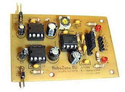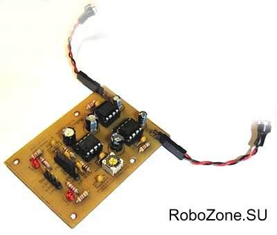
You can set the outputs as analog or digital with JP1. There is a schematic prepared with splan and a pcb file prepared with sprint layout. An experimental binary sound sensor module based on an LM386 audio amplifier and an LM393 binary comparator. The sound sensor circuit is quite simple and the elements are included as standard. Audio amplifiers LM386 are included according to the maximum signal amplification scheme (see data sheet).
The amplified signal from the electret microphones is fed to the two channels of the LM393 comparator. The construction resistor R5 allows you to set the comparator threshold – sensitivity.
Thus, at the output of the circuit, we get two logical signals from the right and left microphones. It is also possible to process the analog signal directly from the amplifiers via the ADC. Outgoing signal options are switched using the two jumpers in block J1.
In the logic output version there is a high logic level in the absence of audio signals (signal LEDs do not light), when the sensor detects any sound, the logic level at the output will be low (signal LEDs turn on).
In the analog output version, the output connector has a stable analog signal that can be processed by the ADC (but the comparator works and the signal LEDs continue to work).
The module is designed for use with electret (condenser) microphones. We tested many different microphone models and settled on miniature ones from mobile phones. They work stably, have small dimensions and have good sensitivity.
The only thing that needs to be decided directly in the design of the robot is the sound isolation of the microphones from each other in order to clearly distinguish the direction to the sound source. The module is designed for use with electret (condenser) microphones.
The sensor confidently responds to explosions, bumps and other sharp audio signals, as well as the human voice. During the experiments, the range of response to sound reached several meters.
The printed circuit board of the module is one-sided divorced and does not present any difficulties in repetition. In the future, another version of the printed circuit board of the sound sensor is possible, taking into account the characteristics of the sound (analog) signal.
LM386 LM393 Audio Sensor circuit

Source: robozone.su/experiments/26-sdvoennyjj-zvukovojj-sensor-na-baze.html Audio Sensor circuit schematic pcb files:
Şifre-Pass: 320volt.com
Published: 2008/08/23 Tags: audio control circuits
USB UART Circuit FT232RL PCB
Due to the fact that many modern computers missing out COM port (on modern laptops almost all) the problem of connecting devices to PCs with MK raises very serious. Ftdichip driver file for your operating system you can download from the site
FT232x FT232R .In family special interest is the FT232R. USB-UART This chip is a virtually ready-made solution, connects to a PC for USB and having the outlet signals UART. These signals are understandable for any MK (including software sold).TX RX . For a simple connection of the two is quite enough of them – TX and RX.
FT232RL PCB USB UART