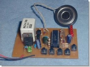
PIC16F84 made a beginning with a simple timer in the introduction to electronic. 2 minutes 45 seconds every 15 seconds to 3 minutes and 45 seconds set in five relays to switch the unit ON. Hours after the relay is set at the buzzer OFF will also be informed.
This has been called in to help make the call letters of his match with the length of Morse from playful buzzer. Morse meet to look like I’m going to be easy to rewrite software.
I set the time switch is pressed which we can see the LED. Time error, we used the RC oscillator clock, and the room temperature (temperature in the lower frequency) in a few seconds. I want to ceramic or crystal oscillator.
Led, Sound Operated Simple Timer Circuit
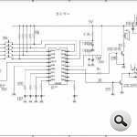
It is to put it with a pull-up resistor of 10KΩ setting switch time (tact SW) to each of PORTA BIT but, PIC will examine whether the ON and which switch first. After detecting a switch that is turned ON, and then ON also BIT7 of PORTB at the same time as the LED light corresponding.
I ON the relay that is attached to the transistor 2SC1815 by it. After you (OFF the relay and LED) OFF, it will sound the speaker ON, OFF repeatedly at the 2SC1815 BIT6 This time the PORTB set time has passed.
The fine adjustment of the set time, you can by rewriting the number of 50msec (CNT50M). The clock frequency is also stable time at the same time a stable room temperature is stabilized.
Şifre-Pass: 320volt.com
Published: 2009/01/23 Tags: microchip projects, microcontroller projects, pic assembly example, pic16f84 projects

PIC16F84 Line Follower Robot Project
Line following robot is the thing to run on the line by controlling the motor of the left and right detected by light, such as infrared drawn in black (7m / m width or so) line. As illuminating the line, I put the light of the ordinary uses wheat balls of 3 volts instead of the infrared, we used (at the Akizuki) CDS with a diameter of 5m / m the sensor this time. The CDS ON motor twin motor gearbox controls the RB4, RB6 of port B sent to RA1, RA2 of port A of the PIC signal ON when out of the line, the signal OFF when applied to the line, and OFF. LED indicates the state.