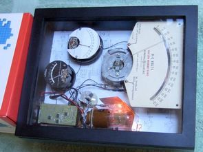
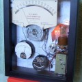
The goal of this project was to build an unusual desk clock using a combination of old and new technologies. Time is displayed using vintage electro-mechanical meters, but the current time is calculated using a Microchip dsPIC processor. Further, a vintage quartz crystal plus a modern op-amp forms an oscillator that is the time base for the clock. All of the components are mounted in a glass-front box, so that both the old and new components are visible.
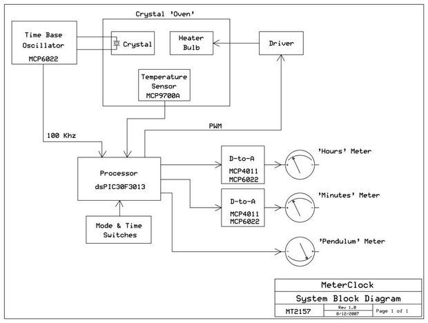
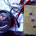
Three vintage meters are used to display the current time. A large meter indicates the hour from 1 to 12, while a smaller meter indicates minutes from 0 to 59. The seconds are not displayed by the clock; instead a small third meter is mounted upside-down so that its pointer can act as an imitation of a clock’s pendulum. The dsPIC30F3013 processor outputs signals to control a pair of MCP4011 digital potentiometers driving MCP6022 op-amps, which then drive the Hours and Minutes meters. In this way, the potentiometers and op-amps form simple D-to-A converters.
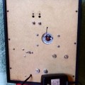
Every clock needs an accurate time base. The Meter Clock uses a vintage quartz crystal plus a modern MCP6022 op-amp to form a 100 Khz oscillator. The oscillator’s output is connected directly to an interrupt input on the processor. Since the dsPIC can run quite fast, it can easily handle the interrupts at a 100 Khz rate, and still have plenty of time for the processing needed to perform the clock’s functions. Due to the physics involved in crystal oscillators, the long-term stability of the oscillator depends on the crystal operating at a constant temperature. The Meter Clock uses an automotive light bulb as a heat source, combined with an MCP9700A temperature sensor, to help maintain a fairly constant temperature for the crystal. A PWM signal from the processor controls the power dissipated by the bulb, and the processor chooses the PWM value using a formula that is based on the latest temperature measurement. The clock’s time is set via two buttons on the rear panel.
Software running in the dsPIC performs all functions, including setting the time, processing the 100 Khz interrupts, displaying the time on the meters, and regulating the temperature of the ‘crystal oven’.
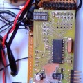
Most of the electronics were assembled on a pair of printed circuit boards. These boards were convenient to use because they were ‘spares’ from another project that was recently completed.
Included in the documentation files is a brief video of the MeterClock in operation. Author: Peter McCollum
The implementation makes use of the following Microchip devices:
• DsPIC30F3013 processor.
• MCP6022 op-amp (two).
• MCP4011-502 digital potentiometer (two).
• MCP9700A temperature sensor.
The dsPIC30F3013 MPU is programmed with a Microchip ICD2, which can be connected to P21. Crystal X1 provides a basic operating frequency of 7.3728 Mhz, which is converted by a PLL inside the MPU to about 118 Mhz. The software blinks the “heartbeat” LED (D2) when in operation. Four switches are seen on the schematic: two momentary pushbuttons for setting the time, and two slide switches (SW1-7 and SW1-8) which can be used to set operational modes or other features. Pushing one of the time-setting buttons on the rear of the enclosure causes the processor to increment/decrement the minutes at a rate of about 3 minutes per second.
dsPIC30F3013 Meter Clock electronic projects files:
FILE DOWNLOAD LINK LIST (in TXT format): LINKS-21792.zip
Published: 2012/05/11 Tags: dspic projects, microchip projects, microcontroller projects
dsPIC30F3013 Meter Clock MCP6022 MCP4011 MCP9700A
The goal of this project was to build an unusual desk clock using a combination of old and new technologies. Time is displayed using vintage electro-mechanical meters, but the current time is calculated using a Microchip dsPIC processor. Further, a vintage quartz crystal plus a modern op-amp forms an oscillator that is the time base for the clock. All of the components are mounted in a glass-front box, so that both the old and new components are visible.
Three vintage meters are used to display the current time. A large meter indicates the hour from 1 to 12, while a smaller meter indicates minutes from 0 to 59. The seconds are not displayed by the clock; instead a small third meter is mounted upside-down so that its pointer can act as an imitation of a clock’s pendulum. The dsPIC30F3013 processor outputs signals to control a pair of MCP4011 digital potentiometers driving MCP6022 op-amps, which then drive the Hours and Minutes meters. In this way, the potentiometers and op-amps form simple D-to-A converters.
MC68HC908QT4 Wireless Acoustic Wave Soil Moisture Detection
The advantage of using acoustic waves to measure the moisture content of soil is that acoustic waves measure the moisture content in a volume of soil that radiates outward from the acoustic source to the detector rather than measure the moisture content at only one point. Each detector is solar-powered and uses wireless transceivers to send the measured data to a server. The heart of each source and detector unit (SDU) is the MC68HC908QT4. The SDU’s acoustic source consists of a piezoelectric speaker excited by a 5-kHz square wave generated by the MC68HC908QT4. The SDU’s detector unit consists of an electret microphone whose output is AC coupled to a high-gain, band-pass filter. The result is then peak detected before being sampled by the microcontroller’s ADC. The MC68HC908QT4 is connected to a Manchester CODEC and RF transceiver for communications with a desktop computer