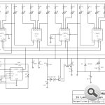
Our circuit was considered little different from the usual circuit. Different from the usual operation of the CD4017 circuit.
Hopefully of interest to you. They remain in one direction lights are burning and burn progressing. Lighting sequence starts from LD1. Ie, starting from the beginning after burning LD16 LD1 goes out.
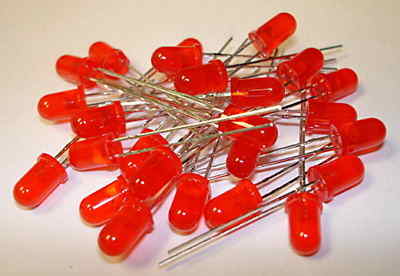
P1 potentiometer to set the speed for burning was made. Request in accordance with the potentiometer or poyansiyometr available. Led by the color of the LED current limiting resistors 330 ohms to 680 ohms should use.
Walking Led Light Circuit Schematic
Published: 2008/08/26 Tags: 555 timer circuits, analog circuits projects, led projects, simple circuit projects

555 Stepper Motor Driver Circuit
Circuit made a long time ago and has been tested. There were a problem in the operation and construction. We must do BDX53 your engine is larger output transistors. 5 and 6 pin motors can be run with the circuit.
Four-ended output transistor to run the engine to be increased. So four BC327 should be added. If you want to add BDX53 transistors transistors used should be BDX54. Our next meeting will present such a circuit.
3006 multi-turn potentiometer P1 type setting using the maximum speed should be done with it. Pots brought to the maximum value of the motor is caused to rotate slowly. P2 according to the minimum value after the engine speed is caused to rotate.