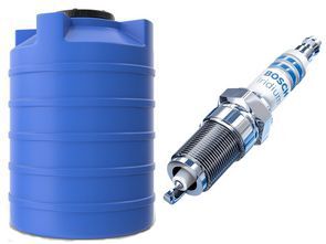
The water sensor is used in various devices in factory, automation, etc. used very often in their work. Mainly for automatic water tank filling, irrigation, heating, control and more. etc., in general, sensors are used where there is water. The use of a spark plug as a water sensor is not new. Some manufacturers even use them in industrial appliances, especially in electric heating boilers.
Automotive spark plugs are used in internal combustion engines, operate at high voltage in various climatic conditions, withstand high pressure. All this ensures their guaranteed operation as water sensors, including for closed-type heating. In addition, the cost of such sensors is very low.
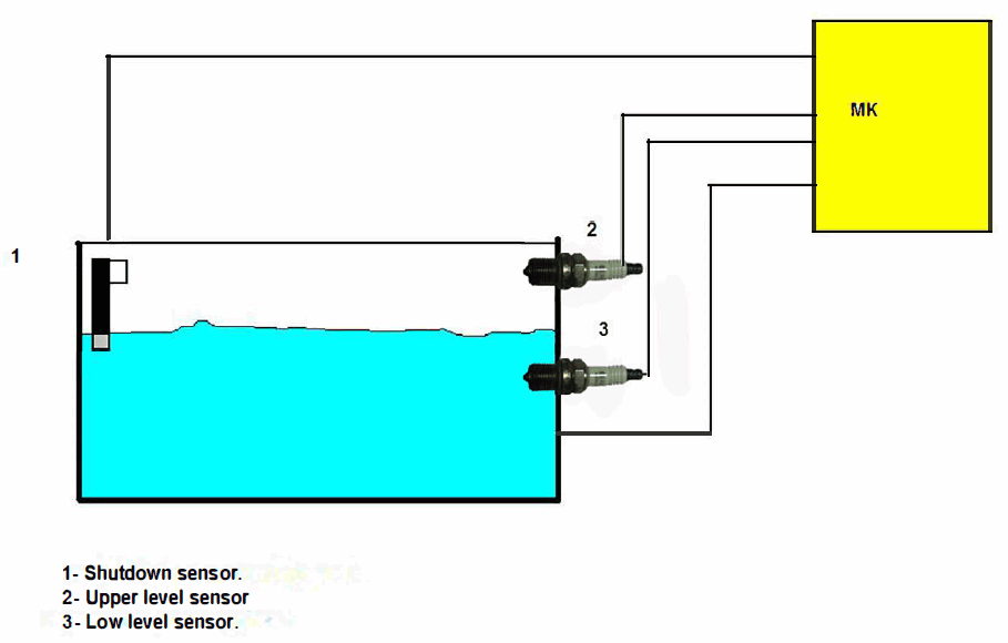
The principle of using spark plugs as water sensors is based on the change in resistance between the central electrode and the body, which we will consider using the example of automatic filling of a vessel.
In this design, imported spark plugs with a built-in resistor in the central electrode are used, the A-17DVRM can be used in the spark plug. The letters RM indicate the presence of a built-in resistor. Such spark plugs are used in injection versions of engines of VAZ origin. The resistance of spark plugs in an aqueous solution will be in the range of 4-6 Kom and a few Mohms in air. Bend or break the side electrode to the maximum value to prevent water from passing between the electrodes of the spark plug. And it will be good if the spark plugs are installed horizontally and fill the inside with sealant.
The figure below shows the connection diagram of the PIC12F675 control unit and the spark plugs to the tank.

The pump will only turn on when the resistance of both sensors is high, that is, when the level of the aqueous solution is below the sensors. Also the state of sensor 3 does not play a role and we are waiting for the water to fill up to the upper sensor, as soon as the level reaches the sensor, its resistance will drop and the pump will turn off. After reducing the aqueous solution, everything is repeated.
For protection, you can install a mechanical shutdown sensor (emergency) or, with a slight change in the program, use another output of the microcontroller and connect another spark plug as a sensor, refusing to indicate one of the LEDs.
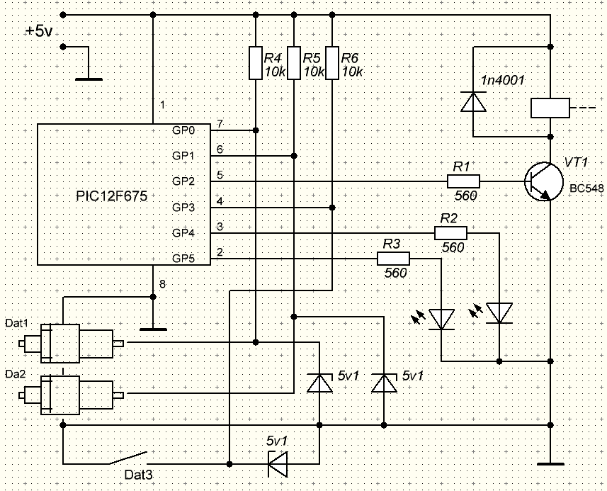
In the design, the corresponding LED will flash when the resistance of the spark plug falls below the allowable value. During normal operation without water, the LEDs will light continuously.
Spark Plug Water Sensor Circuit Diagram

The power supply of the circuit is 5 volts, zener diodes are connected to the input from the sensors for protection. This circuit uses a relay as pump control, but not necessarily a pump. Accordingly, other output stages can be used depending on the load.
The algorithm of the program is very simple: First, the sensors check for a decrease in allowable resistance or a short circuit, and if detected, the corresponding sensor’s flag goes up. The LED of this sensor will then “blink”. Then measurements are made again and the state of the sensors is checked (in an aqueous solution or not) and the load is turned on / off according to the results. If the emergency sensor is shorted to ground, the load will be disconnected.
Source: chipmk.ru (site down)
Circuit .hex, .cof and proteus simulation files 28413a.zip pass: 320volt.com
Publication date: 2022/07/01 Tags: microchip projects, microcontroller projects, pic12f675 projects
Hola,
I will try an interesting project