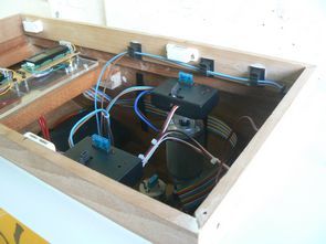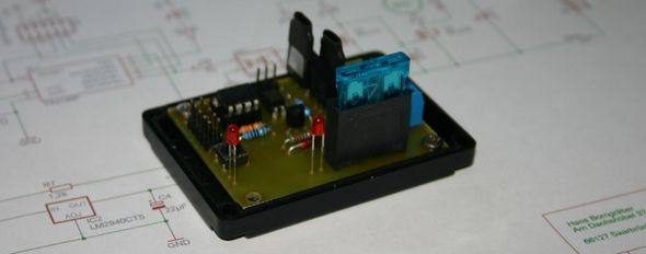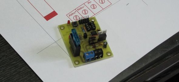
Used in motor speed control circuit microcontroller atmel attiny45p exit number 5 Kubla connected to pin opto pc817 pc817 output while the engine is controlled as isolated MOSFETs have bs170 and irlz34 Attiny45 Pb4 leg control signal number 3 is entered. Circuit driven by motors up to 15 amps. MOSFETs are driven by PWM method pwn frequency 1.8 kHz
Attiny45 LM2940CT5 regulator used to supply PWM motor control Attiny45 value you can use the 7805 Bascom project’s source code schema, and PCBs have drawings


H&H Schottel speed controller
1. Basics
Schottel drives place special demands on model building speed controllers. In particular, very sensitive control in the lower speed range is a must. When looking for a suitable speed controller for our Schottel project, we had great difficulty finding a speed controller that could meet all of our requirements.
The specifications were as follows:
Full control range over the entire travel of the remote control
Easy calibration of the speed controller
No neutral position
No thrust reversal
PWM frequency > 1.8kHz
Logarithmic control characteristic
Control characteristic can be adapted to the motor properties using software
Easy to replicate
Galvanic isolation of load and logic power supply
Maximum motor current 15A
No cooling
We started searching with these specifications and only found what we were looking for in some areas. The attempts with self-made products were mixed across the board. Sometimes the control behavior was not clean or the zero setting was not right or the motors did not run at full throttle etc. There were lots of reasons to think about a suitable PWM speed controller.
When it came to processing the analog remote control signal on a digital basis, we had plenty of experience from the Schottel project. A program was quickly written that resolved the remote control signal cleanly into 256-bit steps. With this digital information, it was quite easy to read a data table that contained the PWM values for the motor. This data table is also the little secret of this controller. With the help of the table, it is possible to adapt the controller to your own needs at any time. The data table has 3 basic areas:
Zero setting area
The area for the motor standstill can be defined here.
Control area
This contains the actual motor characteristic curve.
Full throttle area
This is where you determine when the controller switches to full throttle.
These 3 areas can be individually set and parameterized. For this you need a programming adapter and BASCOM to compile the table. Both are available free of charge on the Internet.
In order to make the speed controller easy to replicate, SMD components were not used and a relatively large circuit board was used. The size of the circuit board was determined by the housing available and proved to be very practical in our case.
Description of the circuit structure.
Circuit diagram of the speed controller
The expert can see immediately that the circuit is divided into 4 areas:
* Power supply
* Processor
* Galvanic isolation
* Power section
2. Power supply
Like all µprocessors, the selected ATTINY45 also requires a stabilized power supply. Since the receiver power supply generally supplies voltages of 4.8 volts – 6.0 volts, a standard voltage regulator (LM7805) was quickly classified as unsuitable at this point. With the LM2940CT5 we used, we were able to cover the required voltage range without any problems, as it is a low-drop voltage regulator that also works at low voltages. The regulator does not need cooling as it is hardly subjected to any load.
3. Processor and software
The ATTINY45 µProcessor used has two timers required for this speed controller. Timer0 operates the PWM divider and Timer1 evaluates the remote control signal that is fed to the processor via pin 3 (PB4). An external clock (quartz) was not used. The calibration LED is connected to pin 2 (PB3). It helps to signal the individual calibration points when calibrating the speed controller. Connector SV1 is the ISP programming connection for programming the µProcessor.
Button S1 resets the µProcessor and starts the calibration process. This runs as follows:
* LED1 flashes until a correct transmitter pulse is received, > 1.5mS. Transmitter control lever at maximum.
* LED1 lights up constantly, the program waits for the minimum transmitter signal < 0.7mS. Control stick at minimum. * LED1 flashes 3x when all signals have been received correctly. Calibration is complete. The speed controller can be used. All functions of the speed controller are monitored by a watchdog. If there is any snag in the program sequence, the "watchdog" strikes and restarts the program. This significantly increases the operational reliability of the controller. 4. Galvanic isolation The galvanic isolation of the drive power supply and logic power supply is crucial for successful speed controller operation. Many speed controllers on the market do not adhere to this principle, which then leads to all sorts of side effects depending on the setup situation. In our case, a Optocouplers are used, which have proven to be very reliable in various CNC projects. The limit frequency of the optocoupler is important when selecting the optocoupler. This is 50kHz for the selected type. This means there is enough reserve to cleanly transmit the 2.5kHz PWM signal to the power section. The 4-pin version of the PC817, which took up little space on the board, was also a great advantage. 5. Power section The power section was implemented with two MOS-FET transistors in order to build an output stage that is as loss-free as possible and therefore produces little heat. The BS170 is only necessary to process the signal coming from the optocoupler. The switching properties of the BS170 make the signal steeper, which means that the power MOS-FET is only controlled for an extremely short time in the partial load range. This makes it possible to do without a heat sink despite the high possible currents, maximum 15A. The two 13 volt tens diodes protect the MOS-FET gates from excessively high control voltages, which must not exceed the 15V limit. The selected logic level MOS-FET IRLZ34 can be fully controlled with a voltage of around 5V. Normal MOS-FETs do not have this property; they require significantly higher voltages to fully control. Therefore, the MOS-FET IRLZ34 in the circuit must not be replaced by another type. The whole thing would simply no longer work. A complex electronic current limiter was dispensed with, as the load capacity of the IRLZ34 is far above the response threshold of the 15A fuse. In the event of a short circuit, as has been involuntarily tested several times :-), the fuse reliably blows and the MOS-FET survives. I have provided LED2 so that you can see whether the fuse has blown again. It remains dark when the fuse has been cost. The vehicle fuse is easy to replace and can be accessed from the outside of the housing. The screw terminals provided on the circuit board layout make it easier to connect the battery and motor. 1.5mm² connecting wires with wire end ferrules are more reliable than soldered silicone cables and are easier to handle in model operation. Diode D1 reliably eliminates the switching peaks that arise from the constant switching of the motor voltage. The decisive factor in selecting the diode is the switching speed <100nS. The current load capacity is secondary; anything from 1A can be used. The main thing is that the diode is fast enough. A 10nF capacitor parallel to the motor winding, directly on the motor, can be helpful in suppressing interference in unfavorable cases. Whether it is necessary must be decided on a case-by-case basis. 6. Replica To make the replica possible for people who are not experienced with electronics, I have dispensed with SMD components. The circuit board layout is optimized in terms of the conductor routing in order to cleanly separate the power and control parts. Please make sure that the MOS-FET and the voltage regulator cannot touch each other. To be on the safe side, it is best to put shrink tubing over them, then nothing can happen. The components are easily available from all major electronics retailers. The software can be requested in compiled and source code form by email. If you do not want to program it yourself, we can help you with pre-programmed processors. These then contain a standard characteristic curve that fits most motors and remote controls. Source: rc-schottel.ch
Şifre-Pass: 320volt.com
Published: 2011/06/19 Tags: avr project, microcontroller projects, pwm circuits
Lowpass Highpass Active Filter Circuits OpAmp
Active filter circuits used in audio circuitry, especially the bass, treble, etc.. general op amp for audio integrated circuits are built on a variety of circuits quite simple overall structure is composed of resistors and capacitors on the main controller integrated op amp. Scheme not specified in the application note this integrated power leg tl082, tl071, NE5532, tl074, tl084, tl081 op amp can be used to integrate the supply leg is in the datasheet information.
Examples and content;