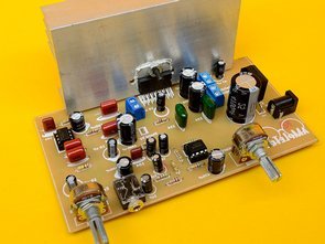
Small amplifier TDA7377 of 15W + 15W + 30W in 4 ohms At the request of our followers, we have developed an amplifier with the following characteristics: The TDA7377 is the main component. It has 4 outputs that can deliver a power of 15W each. we distribute them as follows: First, we have 2 outputs of 15W, which form a stereo amplifier. On the other hand there is another mono amplifier, which is formed by the other 2 outputs in bridge mode, and delivers a power of 30W.
Another additional circuit is a low pass filter that is connected to the input of the 30W mono amplifier. So this one only delivers low frequencies. While the stereo outputs, have a frequency response approximately, from 100Hz, to 20,000 Htz.
Another interesting feature of our design is that it is fed with a simple font. In addition, the preamplifier, the low pass filter, the rectifier source and the amplifiers are all on the same card.
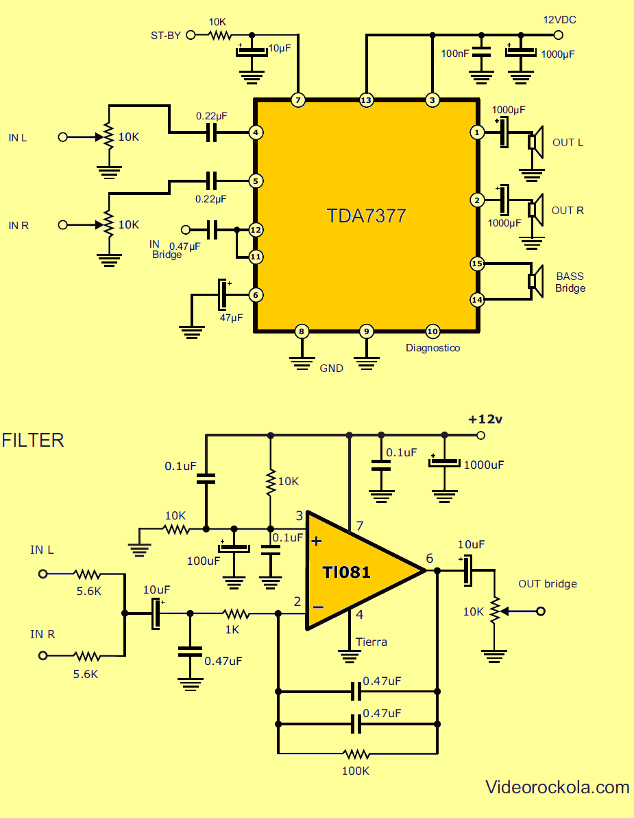
TDA7377 Amplifier and TL081 Bass Filter Schematic

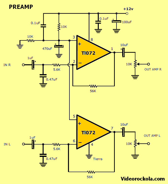
TL072 Preamplifier Circuit Schemetic

The materials for the construction of amplifier 2.1 are the following:
1.pcs TDA7377
1.pcs Tl081
1.pcs Tl072

Resistors

2.pcs 56K resistors (green, blue, orange)
1.pcs 100K resistance (coffee, black, yellow)
5.pcs 10K resistors (coffee, black, orange)
1.pcs 1K resistance (coffee, black, red)
4.pcs Resistors of 5.6K (green, blue, red)

Capacitors

3.pcs 1000uF to 16V and up
2.pcs 100uF to 16V and up
5.pcs 10uF to 16V and up
1.pcs 47uF to 16V and up
1.pcs 470uF to 16V and up
2.pcs 0.22uF (224) polyester capacitors
4.pcs 0.47uF (474) polyester
3.pcs 0.1uF (104) polyester capacitors
2.pcs 1uF to 16 volts and up

Others components

1.pcs 10K double potentiometer
1.pcs single 10K potentiometer
1.pcs 2.54mm 2-pin connector (optional)
3.pcs connectors type terminal block (Block) 2 pins
Heat sink 12 cm long x 5 cm high and 2 cm thick.
1.pcs diode bridge 4 amps forward (comb type)
3.5 mm jack
Cable with 3.5 mm stereo plug on each end.
2.1 millimeter DC jack
2.pcs bases for 8-pin DIP integrated circuit
1.pcs transformer 12V AC and 5 amps. (only in case of the version with source included.) It can also be a 12VDC DC power supply and 5 amps, or a battery.
What speakers should we use?
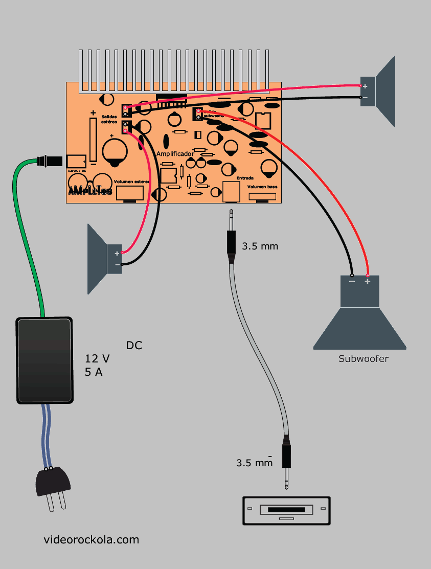
speakers system We take into account that the power of a speaker must be equal to or slightly above the power output of the amplifier. If the stereo outputs are 15W each, then the speakers must support 15W RMS or more. It is advisable to use full range speakers. Another option is to be speakers with good average and high response, since the bass goes separately. The size is to taste. I used 2.5-inch speakers, but I also tried the amplifier with 5.5-inch, 2-way car speakers. For the bass you should use a subwoofer of 30W RMS on, of soft suspension. The size I recommend is 6 to 8 inches
Rectify power supply The integrated circuit TDA7377 is powered by voltages between 12 and 17 volts DC. So we must deliver a continuous voltage to the amplifier. Thinking of being able to use transformers with our project, we include in the card a diode bridge and a capacitor. In the PDF file we deliver two versions of the amplifier 2.1; one with rectifying source and the other without it. However, I prefer the version with a source, even though at any given time, I use a battery or DC switched source. It turns out that the diode bridge, when used with DC current, allows to connect in any polarity. So if someone accidentally connects the inverted voltage, the bridge always redirects to the correct polarity. This works as a way of protection for our amplifier.
Preamp and tone control
There are plenty of integrated circuits operational amplifiers like the TL072. Everyone works in a similar way and many are compatible. The TL072 contains two amplifiers. So it’s used in stereo preamps. It can be replaced by JRC4558, TL082 or NE5532. Each one has its characteristic sound, without demeriting one from the other. The function that it does in our amplifier, is to amplify the signal a bit, since the TDA7377 comes with the fixed gain and is somewhat low. If for example we amplify a cell phone, directly with the TDA7377, its volume is somewhat low. However, when you first pass through the preamplifier with TL072, the sound is stronger. Not to mention that we can modify the gain just by changing a pair of resistances. The gain is left in 10. This is determined by the division of 56K in 5.6K. If for example we want to increase the gain, we can raise the resistance of 56K. And if the idea is to lower the gain, this in case the player has a very strong output and there is distortion, it is enough to lower the value of those same resistances.

As we mentioned at the beginning, our amplifier has a low pass filter. It receives the signal from the already amplified TL072, to be processed. The low pass filter is responsible for restricting the passage of high and medium frequencies, and only allows the passage of low frequencies. The TL081 is a chip that only contains one amplifier inside. Take into account that our amplifier is called 2.1, since the two represents the stereo outputs and the one represents the mono output that only delivers low frequencies to the subwoofer. The cut of frequencies is done mainly by the two capacitors of 0.47uF, which are in parallel with each other, and which go between the input and output of the TL081. If you require more frequency cutting, just raise the value of these two capacitors. The low response of TL081 is better than that of TL071, for this reason we chose this one.
Source: construyasuvideorockola.com
FILE DOWNLOAD LINK LIST (in TXT format): LINKS-26132.zip
Publication date: 2019/06/16 Tags: audio amplifier circuits, ic amplifier
NE556 Speed controller Circuit DC Motors
NE556 Speed controller Circuit DC Motors
The circuit is designed for DC 12V motor and has been tested with miniature drill BOSCH MBM04. Because they can take motor from the source of higher currents, it is appropriate their drive speed pulse while maintaining maximum Tension. Unlike speed control by changing the voltage it has a pulse-width application modulation advantage lower power loss on the regulator end element while maintaining engine torque. Ours the device operates at about 30 kHz.
The primary side of the transformer is protected fuse PO1. From the exit the transformer, the AC voltage is rectified diode bridge D2 to D5 and beyond the DC voltage is filtered by the capacitors C10 and C11. Other filtering the elements in the power circuit are L1 coil and C6 and C7 capacitors to prevent intrusion of high frequency pulses into the IO2 stabilizer input. From the exit the IO2 stabilizer type 78L08 is powered double timer IO1 type NE556.
Schematic Diagram Speed controller Circuit
Amplificateur 2.1 avec TDA7377
Petit amplificateur TDA7377 de 15W + 15W + 30W sous 4 ohms A la demande de nos adeptes, nous avons développé un amplificateur avec les caractéristiques suivantes: Le TDA7377 est le composant principal. Il dispose de 4 sorties pouvant délivrer une puissance de 15W chacune. nous les distribuons comme suit: D’abord, nous avons 2 sorties de 15W, qui forment un amplificateur stéréo. D’autre part, il existe un autre amplificateur mono, qui est formé par les 2 autres sorties en mode pont, et délivre une puissance de 30W.
Un autre circuit supplémentaire est un filtre passe-bas qui est connecté à l’entrée de l’amplificateur mono 30W. Donc celui-ci ne délivre que des basses fréquences. Alors que les sorties stéréo, ont une réponse en fréquence d’environ 100 Hz à 20 000 Hz.
Une autre caractéristique intéressante de notre conception est qu’elle est alimentée avec une police simple. De plus, le préamplificateur, le filtre passe-bas, la source de redressement et les amplificateurs sont tous sur la même carte.
Schéma de l’amplificateur TDA7377 et du filtre de graves TL081
One thing to be aware of, as the TDA 7377 can be differentially driven , the outputs from amps 1& 2 (and 3&4) are out of phase wrt each other.
Hello, thanks for the information.