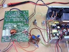
Electronics I first started I remember the days in my workshop to use the current, voltage-regulated supply strong power get the dream 🙂 prices were very high, In this article I’ll share the modification with a very cheap 0.9V..30v 0.1..7 amp regulated SMPS power supply can.
TL494 integrated PWM control that is required when using an ATX P4, P3 power supply and potency, resistance, etc.. as passive elements. Modi circuit current limiting load for a long time I’ve tested the load tests were completed successfully the first was using 12v 50v lamps use electronic load transistor’ve detailed tests.
CAUTION Be careful is working with high voltage capacitor circuit connections Beware + – If you connect the high voltage polarity may be large explosions before running the insured Power Line circuit, protective goggles
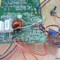
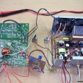
ATX Power Supply Modified
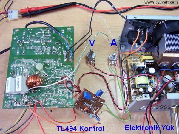
Circuit www.chirio.co Retrieved from sites I’ve done similar before, but these systems are modified to be more simple healthy work caught my attention, but I saw that in the first trial, after struggling for a long time I made the circuit works better. For this reason, I did not kazırl control circuit pcb holes remove plaque formed on a bay, insert the material change was made, though the problem was solved, but with only one capacitor detection has been a challenge 🙂
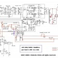
Modified ATX power supply circuit diagram;
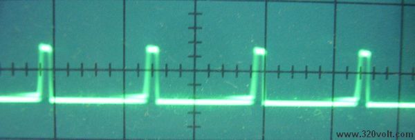
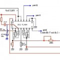
In the diagram drawn with blue color 4.7uF capacitor is not connected to pin 3, the drive transformer is making a lot of noise and quite garbled on the output square wave
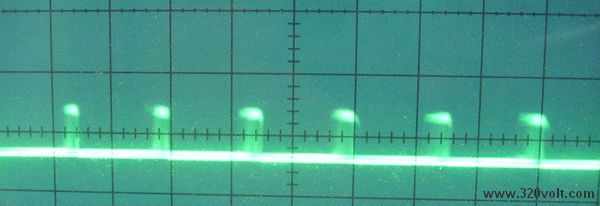
add 4.7uF capacitor
Published: 2010/10/17 Tags: power electronic projects, smps circuits, smps projects, smps schematic, tl494 circuit
PIC Microcontroller-Controlled Electronic Piano Project
Handmade in electronic piano project PIC16F690, PIC16F887 or PIC16F886. PIC microcontrollers can be used to connect to the legs of metal coins used as key microcontroller with ADC circuit 36 is used for touch-key hues quite well
C source code of all the resources given to the Electronic Piano project on the site of the circuit logic and circuit realization detailed information about the operation of the software given.
Electronic Piano Circuit
Hello
I also tried the modification, but the PSU does not have the same values as in the schematic and I still haven’t succeeded. schematically, they are the same, only the values of the components differ. I want to know if the values from the modification are measured in assembly or disconnected and also the voltage of 0.60v is measured with the potentiometer at its maximum value because when it is set to 0 the voltage value changes.
Thank you in advance
Stelian