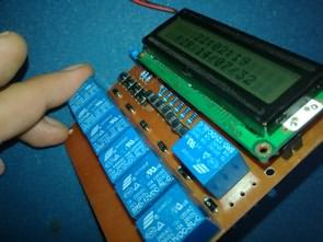
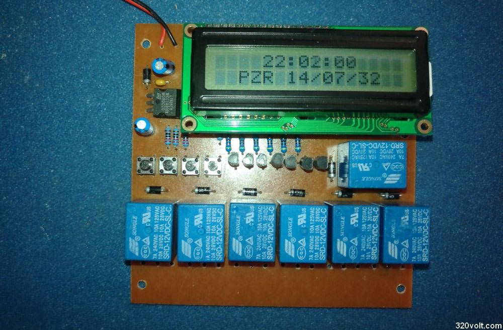
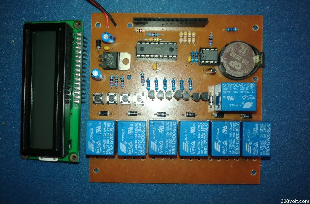
A 2X16 LCD screen is used to display the data based on the weekly timer circuit PIC16F628A microcontroller and the DS1302 real time clock IC. There are different software for using 1.7 Channel without changing the PCB drawing. Relays 12V 10A Clock, calendar, 4 buttons are used for on-off settings of relays. The current drawn by the circuit without starting the relay works with 12VDC between 35…38mA. It is fed through the PIC16F628A, DS1302, and LCD 7805 Regulator IC.
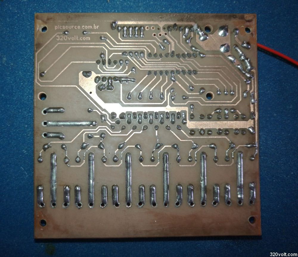
PCB Drawing I designed with Sprint layout 6 PCB Single layer and 10x10cm dimensions
I tested the first version. In the second version, LEDs showing the relay status were added. There are no major changes, but I did not test it. I don’t think it will be a problem.
In the PCB design, I used 3 terminals for all contacts of each relay, various scenarios can be made when the relay is not active, or the sample applications in the Relay and Relay Circuits article can be applied by adding them to the relay outputs.
3V Battery of the type used in CR2032 motherboards. Required for the DS1302 to store the time and date settings.
Weekly timer circuit Water tank filling, garden irrigation, door control, lamp etc. can be used for In addition, it can be used to operate the lights of the rooms at certain intervals when you are not at home for security.
The software has source CCS C code and hex codes. Settings, language change from the software, all the details are in the video.
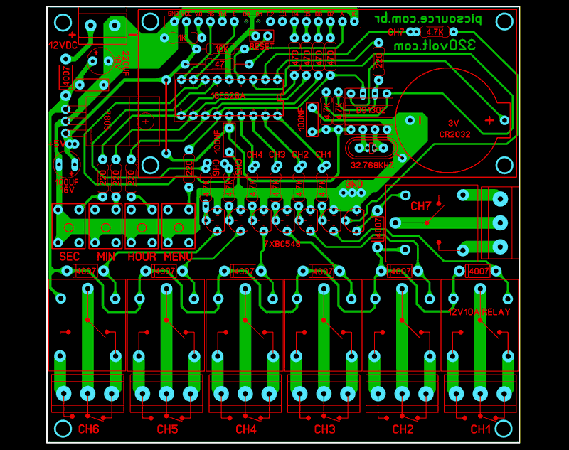
Source: picsource.com.br/archives/7414
PCB and edited codes; 28496a.zip password: 320volt.com
Published: 2022/09/19 Tags: microchip projects, microcontroller projects, pic16f628 projects