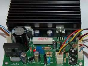
The power supply circuit consists of 2 separate sections, firstly the power stage is based on lm317, tl082 opamp is used for current adjustment, atmel atmega8 microcontroller is used in the current voltage display section, this section may not be used optionally, a simple power supply to try and run various circuits completely independently
Power Supply PS1
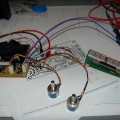
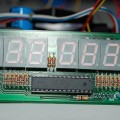
The Power Supply PS1 is a compact power supply with a voltage range of 0 to approx. 24V and the current limit has a setting range of 0A to 1.5A..2A – depending on the transformer used. The current and voltage are displayed using six 7-segment displays, which are controlled by an AVR ATmega8. The display is only optional, so not absolutely necessary for the power supply to work. But who wants to do without a display 😉 One advantage of this power supply is that it only needs a single supply voltage. This means that a small transformer can be quickly obtained from a dismantled device.
To set the voltage / current, I use 10-turn potentiometers. These are relatively expensive at around €5, but once you have experienced the advantages of multi-turn potentiometers, you won’t want to miss them. Of course, simple, inexpensive potentiometers can also be used.
All required files can be downloaded here:
Eagle files, layouts, documentation and software (04/26/2009)
FAQ
Does a voltage regulator have to be insulated?
Yes, the 7805 has to be insulated from the heat sink.
How is the voltage display calibrated?
The voltage display is set using potentiometer R11.
How is the current display calibrated?
A multimeter is connected to GND at J2-2 and the voltage is set to 0V using R2. No load (consumer) may be connected to the output.
In the adc.c file, line 57, any deviations in the current display can be calibrated. (Resistors with a tolerance of 1% result in a display deviation of max. approx. 10mA.)
ERRATA
04/30/09: C12 100nF must be replaced by a 22µF 16V electrolytic capacitor! Plus here to ground. This is the -1.25V reference voltage.
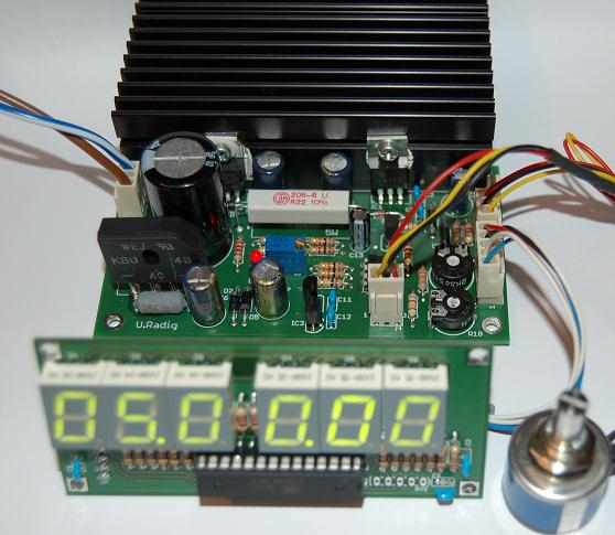
All the source code to the project and eagle diagram, pcb drawings have Source: ulrichradig.de alternative link:
Şifre-Pass: 320volt.com
Published: 2011/05/11 Tags: atmega8 projects, avr project, microcontroller projects
Crossover, Active Audio Filter Circuits NE5532 Opamp
Active filter circuits NE5532 opamp made using the 2 and 3-way versions available (low pass, band pass, high pass) also opamp in the calculation formulas and examples in the scheme’s entire circuit of the PCB drawings are operating voltage of + – 15v symmetric