Turbo C Of dc motors speed control done in two ways first excitation current by modifying it happens for the moment does not concern us Another method applied voltage by changing the motor speed can change thus this method is the usage of applied voltage DC (Direct Current) chopper (Converter) circuit is replaced by.
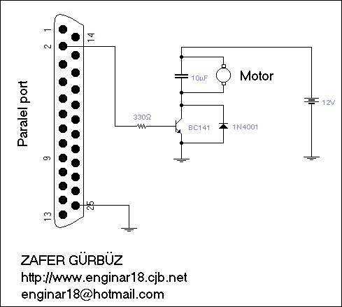
Parallel Port DC Motor Speed Control Schematic

A transistor is used in the chopper circuit, this is a tronsistor with a switching frequency of at least 10kHz and Ic (collector current) to meet the current drawn by the motor. The operating frequency of the transistor is important because the higher the turn-on – output speed, the more healthy the output voltage of our chopper can be adjusted.
The basic logic is to put the transistor in the circuit on and off according to the conduction and cutoff times determined by the output we get from our port. The output of the chopper circuit changes with the transmission and cutoff time of the chopped voltage.
We control the parallel port with the program we wrote in Turbo C. According to the transmission and cut-off times determined in the program, it is to send a signal at Logic 1 level to pin 2 of the parallel port, and when we send 1 numerically, +5V will occur at the output of the port, which will drive the transistor and enable it to operate. The logic 1 execution time determines the transmission time.
If the transistor is desired to turn off, when we send the number 0 to pin 2 of the parallel port through the program, the BASE current of the transistor will be cut, and the transistor will go off. Logic 0 time also depends on the time the chopper stays at zero.
If we want to obtain a small voltage at the output of the chopper, that is, if we want our motor to rotate slowly, we reduce the transmission time of the transistor and extend the time it is in the cutoff. If we want to increase the voltage, that is, if we want to increase the speed of the motor, increase the transmission time of the transistor and reduce the cut-off time.
is the required action.
Speed Control Turbo C Software
#include<dos.h>
#include<conio.h>
#include<stdio.h>
void main(){
int i,j;
clrscr();
printf("\n\n\nport 'a information has been sent");
for(i=4;i>0;i--){
for(j=0;j<250;j++){
outport(0x378,1);  //Parallel port to send the number 1
delay(3);                       // 3 ms to wait transmission time
outport(0x378,0);  // Parallel port to send the digit 0
delay(10);         // Wait time 10 ms segments
}}
outport(0x378,0);  // parallel port reset
}
source crosswinds.net/~enginar18/dcmotorhiz.htm
Published: 2008/11/23 Tags: analog circuits projects
18-Pin Microchip PIC Experiment Boards Project
A Microchip PIC16F628 PIC16F648 PIC16F628 PIC16F84A PIC16F84A 18 pin PIC16F648 PIC `s simple handy series of experiment, development board