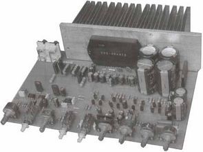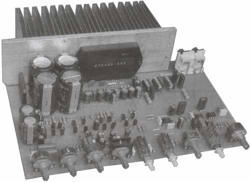
STK400-290 can deliver 3X 50W power, a quality 2+1 amplifier circuit is made by adding a bass filter circuit created with tone control transistor and NE5532 4558 ops.
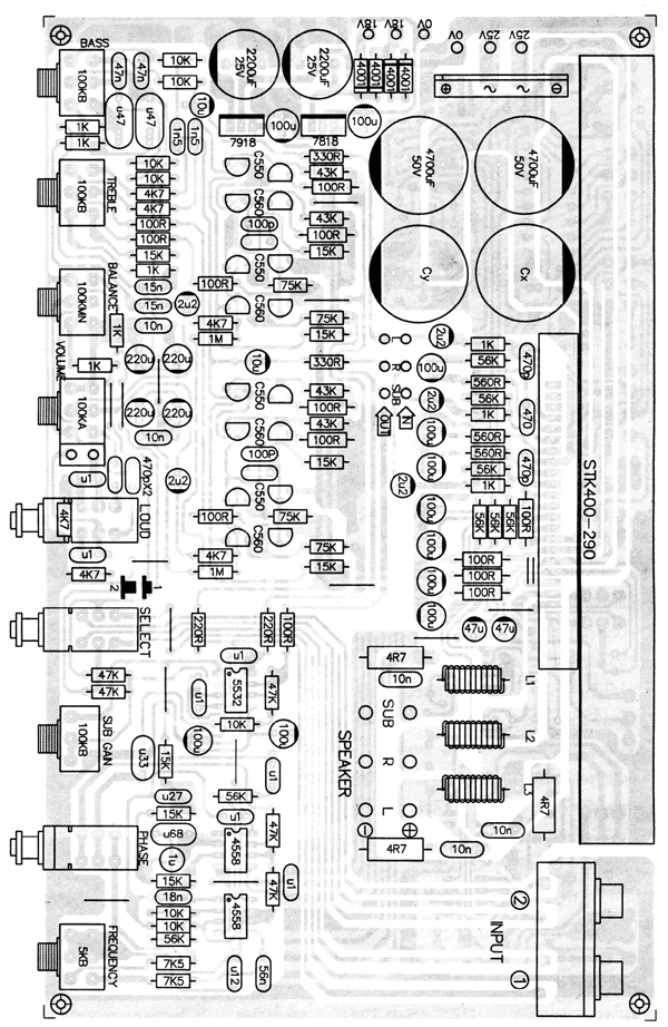
Also, input selective bass amplifier and tone control have Loudness feature. Material values are not selected in the circuit diagram, but the values in the pcb top view it is read clearly, there is also a list of materials, a nice design..
Tone Control Features; Low noise Frequency response range 20Hz – 20kHz, harmonic distortion below 0.001% 20Hz – 20kHz, Maximum output voltage 14 V rms at 20Hz – 20kHz, Input sensitivity 50mV, Speed increase/decrease 17dB at 20Hz at treble + Hz
Different amplifier ICs can be used instead of STK400-290, for example 4 TDA7294 two for right and left channels and the other two for subwoofer with bridge connection.
In this case, STK400-290 and related electronic components will not be used, only audio inputs will go to new amp modules or PCB can be rearranged. Transformer used for 2x24v ac 3+3 amps and 2x18v 400+400 800ma double winding power
STK400-290 Amplifier Project


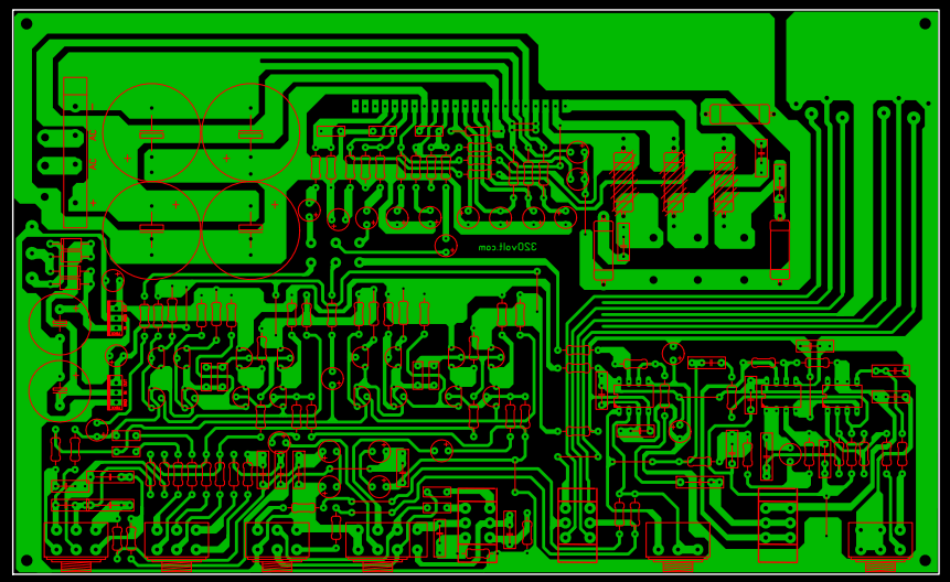
Note: PCB drawing of STK400-290 2+1 Amplifier Circuit was redrawn with Sprint layout 6 program by copying from the picture. Those who want to apply the circuit should check and print according to the original PCB drawing.

STK400-290 Tone Controlled Amplifier Circuit schematic pcb files:
Şifre-Pass: 320volt.com
Publication date: 2009/02/25 Tags: audio amplifier circuits, ic amplifier
The simplest radio circuit
5 piece kit consisting of the first half pretty simple and inexpensive radio circuit with a stylish casing made of wood and plexiglass think should be reinforced with output amplifier fm radio circuit has two different 🙂
simple radio circuit