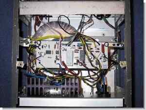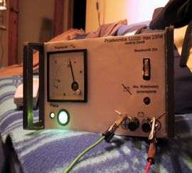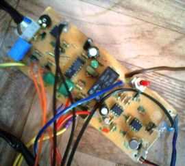
230 Watt sine wave inverter SG3524 PWM control circuit integrated in the project used a lot in various power UPS uninterruptible power supply on the market I have ever seen in an inexpensive components to bolc
The inverter circuit 12 volt + entry in the D1 diode reverse polarity protection ensures after the LM741 opamp made with low-voltage detection circuit, this chapter battery voltage of 10.5 volts drops below PK1 relay and stops functioning for cooling fan control section also LM741 made by
CNY17 opto with 220 volt ac output voltage is stable solids added to the feedback provided to the collapse load is connected to 220v ac output


Driver IRFZ44 IRF540 power MOSFETs can be used instead of 2x IRFP140N/TO In response, I would suggest at least out of IRFP3710 10Volt 2x 250w 200w suggestion recommend you use a transformer transformer outputs also different from one extreme to be careful. After running the circuit to measure the output voltage True RMS measurement capability should use a measuring instrument in a very multi meter is specified, this feature appears incorrect values in normal measurements with multimeters
12V to 220V Sine Wave Inverter Circuit Oscilloscope
Improved automatic battery charger circuit, the output would be more useful if added to the EMI filter. Pdf file in the circuit diagram pcb drawing materials list and detailed descriptions available writings google translate and can translate google the hard work you untie the Turkish translation a bit confused less by reasoning unraveling translated the language selection section “Detect language” Set
At the output of the inverter circuit, some of the devices that can be used
• Television radio and so on.
• Lamps
• Power Tools
• Computer
CAUTION Be careful is working with high voltage capacitor circuit connections Beware + – If you connect the high voltage polarity may be large explosions before running the insured Power Line circuit, protective goggles
source elektroda.pl SG3524 PWM Sine Wave Inverter schematic pcb files alternative link
Şifre-Pass: 320volt.com
Publication date: 2009/07/02 Tags: power electronic projects, sg3524 circuit, smps circuits, smps projects, smps schematic
5+1 Home Theater System SADC Preamplifier Circuit
Quality hi-fi quality 5.1-transistor preamplifier circuit design have given all the details of a list of materials, box dimensions, PCDs, drawings, sound dB details, measurements, notes etc.. BF245C circuit, 2N3019 (2N1711 can be used instead) transistors based on a single source of supply voltage 60V DC. We also applied on the source site has a lot of projects in the preamp amp lamp
Preamplifier SADC Circuit
Mentor , please my desire is to build this as my project, power inverter, circuit 3524
PWM, sinewave, I need every details to realize this, circuit is important
Hi,
download .zip file all details, circuit diagram in file
Please could please permit me to download your pure sine wave inverter circuit sg3525.
Could you please send me the diagram for a try thanks.
the file is given at the end of the article. pass: 320volt.com
If I download, I do not see any items included, may be my phone apps cannot open it, I think.
setup winrar app https://play.google.com/store/apps/details?id=com.rarlab.rar&hl=tr&gl=US
+ sending files via email as an attachment. good work
Please I need your sg3524 pure sine wave inverter circuit diagram for a try. If you could kindly send it to me.
I received the email from you yesterday with the file, thank God for your support and help. I wish you the best in your business endeavors thanks.