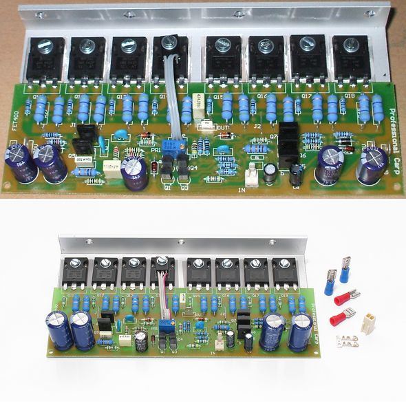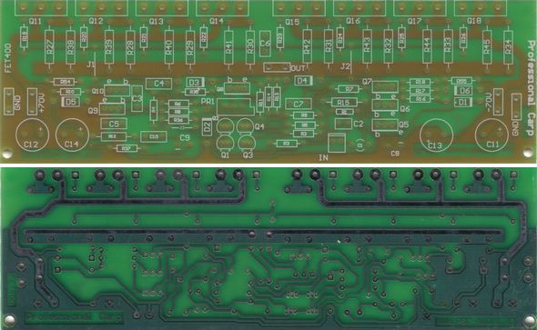
All the details of FET400 Mosfet amplifier circuit diagram, PCB, layout description and high resolution images (hq) have 8 ohm speakers with 263 watts RMS and 350 watts into 4 ohms 6 ohms and 406 watts rms power can give. Made the same circuit on the audio input adder circuit using 2 800W power ratio can be 0.5% THD on fet400 4 (n-channel) and IRFP240 (p-channel) MOSFETs used IRFP9240.
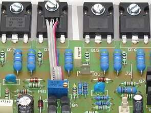
Amp’s quiescent current 60mA .. 120mA adjustable between circuit operation voltage of the lowest + – 30 volts DC maximum + – 70 volts DC appear in the image MOSFETs on the mounted mje340 transistor themed as a spectator, as used in the same way must be installed


Hi-Fi Amplifier 400 Watt PRO (1 x 400W RMS)
PCB board dimensions: 165 x 51 mm
Fixed output power: up to 600 Watt RMS (1 x 600 W RMS @ 10% THD)
Low Total Harmonic Distortion (THD)
Audio IN input level for maximum output power: Vin = 1 Vpp
supply voltage: (min. ± 30V … max. ± 70V DC)
Consumed current: max. 6A
Current consumption when empty: 60… 120 mA
Output power with 0.5% total distortion (Watts RMS): Vin 1Vpp, Vcc = ± 70 V, Rout = 8 Ohms – 263 Watts Vin 1Vpp, Vcc = ± 70 V, Rout = 6 Ohms – 350 Watts
Vin 1Vpp, Vcc = ± 70 V, 4 Ohms – 406 Watts Frequency range: 16Hz… 35KHz. (±3dB)
Şifre-Pass: 320volt.com
Published: 2011/08/21 Tags: audio amplifier circuits, transistor amplifier
340W MOSFET Power Amplifier Circuit APEX HV 23
Apex 340W MOSFET amplifier circuit power stage 4 in the IRFP240 (N-Channel) and 4 IRFP9240 (P-Channel) MOSFET used 8 ohm speakers with the RMS 240W into 4 ohms and 340W Power can give printed circuit resettle plan and scheme, further circuit protection floor is in rectifier and filter circuit this section, but only residential floor plan has the same print but in the material values and PCB layout drawings for printing as it seems What can be copied.