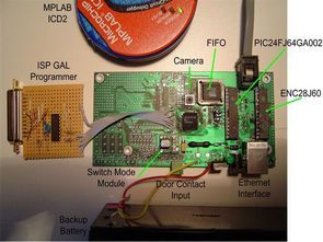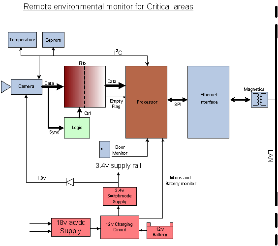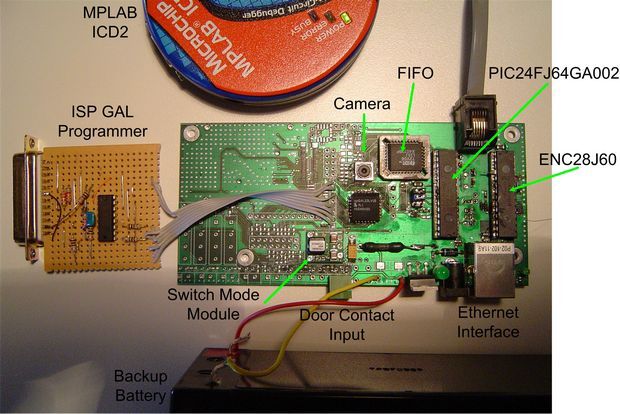
Custom designed hardware, presented using the eligible Microchip 16-bit MCU PIC24F64GA002, has been developed for the Microchip design contest to implement a video based remote environmental monitoring system for use in critical areas. The design has incorporated an on-board video camera, battery back-up and a number of Microchip devices to obtain a comprehensive environmental monitor. The Ethernet interface is achieved with the Microchip ENC28J60 which is a Stand alone Ethernet controller with SPI interface. The temperature is measured with the Microchip MCP9800 which is an I2C based temperature measuring sensor. The Microchip 24LC16BT I2c based EEPROM has been used to store the user configurable high and low temperature set points as well as the point at which image differences will generate an alarm. DHCP has been used to obtain an IP address automatically from a DHCP server.

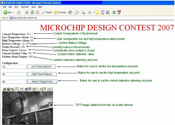
From an onboard HTML web page (see Figure 1) the user is able to remotely connect to the system to get the following information:
• A Video image of the environment
• The current temperature at the location
• Indication of whether a mains power failure has occurred
• Indication of the voltage state of the backup battery
• An open/closed state indication of a door contact

The system is also capable of providing alarming information when the measure variables have passed certain alarming set points. The alarming information is output using a TCPIP socket to a Telnet type application. This information is only relayed when an external connection exists. Table 1 shows the alarming strings that have currently been coded. The user is also able to set the alarming set points from the onboard HTML webpage (see Figure 1). The alarming set points that are user configurable are:
• High and low temperature alarming set points
• Amount of video motion required before alarms are generated
Mains failure and battery low voltage alarm conditions are also present but these alarming points are not user configurable and are compared to hard coded alarming values.
TCPIP Socket String Description
VIDALARM Video motion detection has gone into alarm
POWERALARM The main power has failed
TEMPALARM The temperature has gone above or below the temperature set points
DOORALARM The door contact input has changed state
BATALARM Low battery indication
The 16-bit architecture of the Microchips processors are ideally suited to image processing as has been demonstrated by the implementation of a simple video motion detection algorithm. Now that the video capture system hardware has been designed more complex image algorithms can be implemented. The large 8 Kbyte on-board RAM ensures that the processing algorithm can be achieved entirely within the onboard memory, thus reducing the need for any external memory. The large onboard flash also implies that the entire TCPIP stack, image processing algorithms and HTML web page can be implemented on the device, hereby also cutting down on external program memory requirements.
The video motion detection algorithm runs continually in the background comparing a current captured video image to an older reference video image. If differences are evident when the two images are compared an alarm is generated. Author: Kevin Tiplady

PIC24F64GA002 ENC28J60 TCPIP stack Remote Environmental Critical Area Monitor electronic projects
Şifre-Pass: 320volt.com
Published: 2011/07/10 Tags: microchip projects, microcontroller projects
Buck-Boost converter circuit 555
Buck Boost Converter circuit +12 V input voltage (10v. .25 there may be between)-13v as a favor from the (inverting) power 250mA optionally output voltage D2 zener diode changing can be increased or reduced (5v … 20v) circuit operating frequency of 12kHz pcb design (sprint layout) done according to the size quite small sMD components