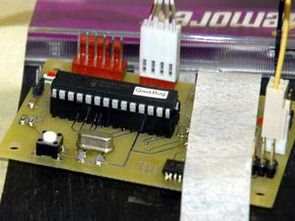
PIC PID Microcontroller A closed loop PID controller application for speed control of DC motors. The l298d driver integrated circuit was used for motor control. The PID control circuit is based on the pic18f252 microprocessor. The software is prepared in C language. There are all the details (in English) and the source codes and flow diagrams.
Doing the project really led me to systems and control theory. A friend and I implemented a fully functioning PID motor speed and positioning controller on a PIC MCU. This is a very comprehensive guide to building a robotic peripheral.
I have done many projects as part of the IEEE hardware team, but this is the one I am most proud of. This was a PIC-based system that implemented a closed loop PID controller for position and speed control of two DC motors. In addition, the control loop can be set to induce arcs.
The system was designed as a peripheral for another processor, so it also had an SPI command interface that allowed it to communicate at a high level while controlling the motors at a low level. The peripheral had a serial console that allowed you to set up, test, and drive the robot.
In order to complete its mission, it needed to precisely control the robot’s speed and position. Since so much of this robot’s existence was done computationally, it was especially important to maintain accurate information about the robot’s distance traveled.
To give the robot all of these features, we designed a special subprocessor dedicated to low-level control of the two main motors. We implemented this system on a Microchip PIC18F252. This processor was placed on the same board as the motor driver, which received control signals from the controller and used them to actually drive the motors.
Our subprocessor monitored the motors and applied appropriate pulse-width modulated (PWM) signals to ensure they reached their destination. This controller also had the ability to communicate with the primary controller to receive speed and distance commands, as well as report back successful speed and distance to the command processor.
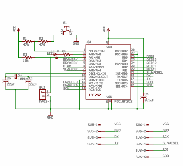
PIC18F252 Microcontroller Pid Control Schematic
Feedback
To get speed and distance information from the motors, we purchased motors with built-in encoders that output a quadrature encoder interface (QEI) signal. This signal consists of a sequence of two pulses that tell us when the wheel has moved a fraction of a revolution and the direction of motion. When channel A transitions from low to high, the value of channel B is checked to determine the direction. A sample QEI output can be seen below.
The Quadrant Encoder Interface (QEI) Motion controller was able to intercept low to high transitions from QEI on channel A and generate an instantaneous estimate of speed and direction by tracking the number of counts obtained in a given time interval. We used this information as input to the control loop that determines and compensates for errors in speed or distance.
Control Loop We implemented a PID (Proportional, Integral and Differential) control loop to control the speed of the motors. The speed of the motors is manipulated by changing the duty cycle of a PWM signal generated by the processor. The duty cycle of this signal is known as the control value. Below is a functional diagram of the control loop.
PID Flowchart
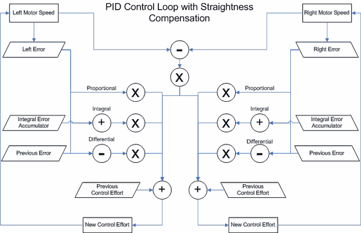
This algorithm first determines the difference between the commanded speed and the actual speed. This value is known as the error. The integral error is determined by adding the error to an accumulator and the derivative error is calculated by subtracting the error from the previous error.
Each time the control loop is executed, each of these errors is multiplied by a gain constant that is adjusted to optimize the response time and accuracy. These errors multiplied by the gain constants are then added to the control value to calculate the new control value.
In this way, the control value is constantly updated according to the response of the motors. This allowed the motors to move at the desired speed despite drift, obstacles or other unexpected road conditions.
A final compensation factor is added together with the P, I, and D errors. This is an error caused by the inconsistencies in the two wheels. This helps to keep the robot straight by compensating for the factors that slow one wheel down but not the other.
Position Control This was accomplished by controlling the speed based on the robot’s proximity to the desired position. The motor controller could receive commands from the main processor telling it how many “ticks” to move. This value corresponded to the exact number of QEI pulses the robot had to move.
The exact distance represented by each tick was determined by the resolution of the encoders and the diameter of the wheel. Our control system could respond to 2944 ticks per revolution. With wheels 2.2 inches in diameter, the total distance per tick was 2.346 × 10⁻³ inches. This made very detailed motor control possible.
The position control algorithm allowed the robot to approach the target distance at any speed It provided the ace. Then, as the target approached, it would slow down so that it could stop correctly when desired. This was achieved with a simple algorithm diagrammed below.
Position Control Flowchart
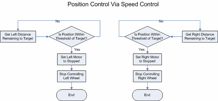
The position of the motors was monitored and continuously updated in local variables. When the motors reached a certain threshold distance before the desired position, the position control part of the algorithm would command the motors to stop. This would ensure that the robot would be in the desired position when the motors slowed down and reached zero speed. These two systems were independent for the left and right wheels, so that they could be commanded to move different distances for turning.
Communication These capabilities provided the robot with the tools it needed to control its speed and distance. However, to be truly useful, this subprocessor needed to be able to receive commands from the main processor and provide back information about the motor status.
We achieved this using an SPI (Serial Peripheral Interface) communication protocol. Communication was message-based. The main processor can send eight-byte messages to the PID controller. These messages begin with a one-byte opcode that tells the subprocessor what kind of command the message contains. The next seven bytes contain data such as the desired speed or the desired distance to travel.
The subprocessor can send back eight bytes at a time, holding the current speed and the total distance traveled. With the ability to control speed, position, and communicate with the main processor complete, the motion control system is almost complete.
Tuning the Control The final step was to tune the PID control algorithm. This is accomplished by adjusting the gain constants that each error is multiplied by before being added to the previous control effort. This is a complex process that is mostly achieved through trial and error.
Another tool that helped was to use GNUplot to make graphs of the debug data output by the PID controller. This allowed us to see the interaction of different errors. This interaction can be seen below.
Graphics Used to Set Up the Controller
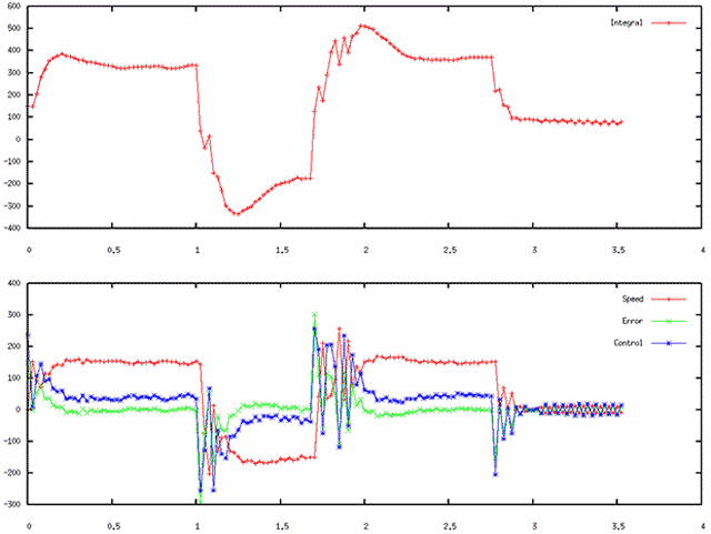
The PID controller was simplified by developing a separate user interface from the main processor to set up the processor. This allowed the control system to be serially tuned by adjusting the gain constants stored in the EEPROM.
Once the motor controller was fully tuned, it performed very well and provided excellent speed and position control for the robot without disturbing the main processor with this low-level task. The full code for this motion controller is below.
Motor Driver
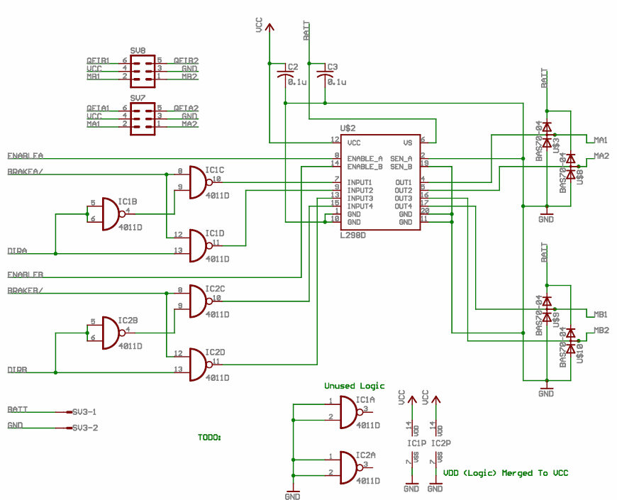
The motor driver needed to amplify the logic level PWM signals to the 9.7V motor using PWM at up to 3A. To achieve this we used an L298 H-bridge chip. We added some handy plugs for programming, connecting to other processors, and plugging in the motors and power.
Final Thoughts
I was really happy with this project. Below you can see me and Jacques giving our ‘gang sign.’ In case you can’t read it that says “PIC” … as in the PIC chip we wrote the PID controller on.
But more seriously, there were some valuable lessons learned. I really got the hang of SPI. It may have been better to use I2C for this, but I’ll have to save that for next time. I also got really turned on to systems and controls. The idea of a closed loop control system that uses its error to correct itself is very clever and elegant. I strongly recommend taking a class on systems and controls if you haven’t yet.
Another thing I’d like to share is *ALWAYS* program in C. Assembly is sooo much more annoying. We started the project in assembly and quickly realized that things were getting out of hand so we switched to C (God’s own language) and everything started going very smoothly.
If I had it to do over again, I might also make the position control better. As it was, you really needed to tweak constants every time you changed the default speed of the system. It was highly accurate, but it would be a little more robust if I had implemented a PID position control algorithm in addition to the PID speed control algorithm.
Source: shawnlankton.com/2005/03/pic-pid-controller/ PID Control schematic Circuit source code alternative link:
Şifre-Pass: 320volt.com
Published: 2010/05/30 Tags: microchip projects, microcontroller projects
70W Subwoofer Amplifier Circuit TDA1562Q Bass PCB
TDA1562Q integrated with the quality and output power will be longer as popular had previously shared different applications. In this application, a 70-watt subwoofer for bass amp circuit made.
Bass TL072 opamp to control the input filter based on the frequency with potency (20Hz – 200Hz) and sound settings can be made available in the filter circuit devrelerinde different amp. PCB design quite elegant and useful resources on the eagle files provided
Car Subwoofer Amplifier