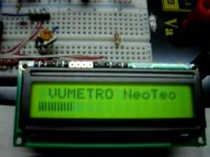
It was a suitable title for the circuit, you can make a simple voltmeter or vumeter circuit with a 2×16 LCD display with pic16f877, the system is almost the same, the circuit is established with the same software picbasic, lcd, pic and a few passive elements.
The creation of the application is very simple: it is done with any microcontroller with an analog input to be able to make measurements of the magnitude you want to represent. What is always different will be the stage before the microcontroller’s input, but the ultimate goal is to convert the data to be displayed into a variable with a deviation between 0 and 5 Volts. As always, we recommend using a 5.1 Volt or 5.6 Volt zener diode at the input to protect the microcontroller.
If you want to use the development as a simple voltage indicator, it will be enough to make an input resistor divider to adapt the levels to those supported by the selected microcontroller. If the magnitude to be evaluated is different (temperature, current, RF signal, etc.), you should add a circuit that can convert that energy into a variable voltage between 0 and 5 Volts.
LCD Level indicator Circuit
Since the range of possibilities is too wide to cover all possible applications, you should choose the most suitable input interface according to the needs of your structure. Then, you need a simple four-bit connection to an alphanumeric display that can have as many characters as you want, and of course a power supply according to the circuit you want to develop.
We define the PIC to be used and its corresponding crystal; then the LCD connection, the operating parameters of the analog-digital converter and the variables we will use in the program. Up to this point, everything is very classic. The “different” commands that we can see in the listing start with the PRINT $FE and PRINT $0 instructions. When a PRINT command is not followed by a position indicator, it becomes a direct command to the LCD. In the special case of PRINT $FE, it refers to any action that we are trying to perform with a blinking cursor (intermittent view) on the screen.
For example, PRINT $FE, 1 would be equivalent to the expression CLS (clear screen); PRINT $FE, $0E would mean that a blinking cursor (simulating an underline) will appear under each character on the screen. Like these, all special PRINT $FE commands are well explained with the help of compilers (Proton Lite in this case). On the other hand, PRINT $0 indicates that we will write directly to the CGRAM of the display, while the termination $0 at the end of the instruction performs the function of terminating (NULL) the data string sent. Within these commands, REP c/n tells us that we will send the character c to the display n times.
What we will do in the measurement loop is to take the current value of the selected analog input, which will have a range between 0 and 5 Volts and will have a numerical value between 0 and 1023 inside the PIC. For the correct conversion, we should use the following mathematical calculation:
DATA = (DATA * 500)/1024
Since we will be leaving the capacity of a WORD variable while multiplying by 500, we will always stay within the size limit of the variable by using the mathematical operation “*/” (Multiply Middle Operator) that Proton provides us. . Accordingly, the result of the expression is as follows:
DATA = (DATA */ 500) >> 2
In this way, working with fractions is shortened to a single command and will take up valuable space in the amount of BYTE used, which we sometimes cannot afford to waste.
Then we enter the number of segments that our LCD will occupy in the SAMPLE variable. In the case of 16 characters, it will be 48. Therefore, the result obtained by dividing the obtained sample by 3 will be the FULL number of characters (three segments), while the results occupying the PARTIAL variable are those that do not obtain a section equal to the remaining zero. This is known in Basic as the “MODULUS //” operation. Here we will enter characters with two and one single segment. Finally, we complete the display by leaving enough space to fit in the PAD variable. When combining the print of the line, we insert the full characters repeatedly (REP $03\COMPLETOS); then comes the PARTIAL, which will always be only one (either one part or two); and finally a repeat of PAD (blank spaces) until the end of the line.
This would be one of many possible ways to create a level indicator bar in Basic (Proton). Thus, we can combine an audio vumeter, a water level indicator, a device that measures the intensity of radio signals, a voltmeter, and anything else that requires a dynamic measuring instrument where feelings prevail over cold numerical information.
Şifre-Pass: 320volt.com
Published: 2010/07/10 Tags: microchip projects, microcontroller projects, pic16f877 projects, picbasic pro examples
GTP USB programmer Circuit
Archive while stirring drew my attention the famous GTS USB programmer files a timely places download’m now a classic programmer circuit was but a lot of users have all of the files that to share Isetan I in a corner, Let there;)
USB programmer PIC microcontroller and memory EEPROM with a single integrated circuit does not require an additional power supply.