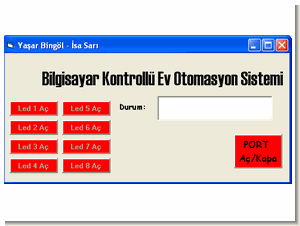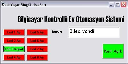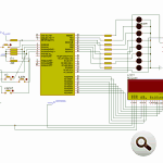
Basic home automation project can be an example with all the resources INFINITY side @ picproj on the forums shared software ccs-c prepared by the source. C. H ccsc codes isis simulation files and visual basic interface of the control program. VLPs,. Frm,. VBW code’s pic and computer via the serial port using the supplied communication with MAX232.
In the pic with the program output status LEDs on the control LEDs can be seen ruling out different elements strengthened outputs (relay, triac, thyristor, etc..) Can be controlled operation information is displayed on the LCD.
authors: Yaşar BİNGÖL İsa SARI
Home Automation Circuit

home automation project schematic source code files:
Şifre-Pass: 320volt.com
Publication date: 2009/07/03 Tags: ccs c examples, microchip projects, microcontroller projects, pic16f877 projects

PIC18F2550 USB isolated Triac Control CCS C Visual Basic
Now you have to wonder to advanced pic controller was quite popular among them PIC18F2550 USB pic18f2520 a good example on how to control the output with the MOC3042 opto triac driver output isolation is being provided and TIC236M working with the 220v loads can be controlled
Source article with triac drive circuit used in the lamp up to 100W without cooling, heating and so on. As indicated loads can be controlled with a coolant 10A (2300W) also isolated driver circuit that can be used in the other controller output