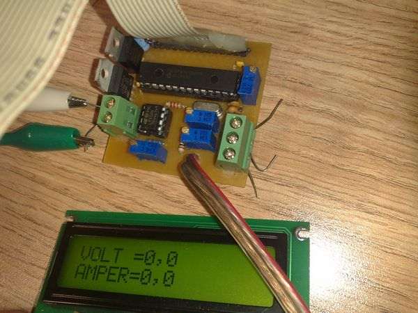
As soon as a circuit to do. Volt ampere meter circuit 2 × 16 LCD screen displays information on the voltage and current used PIC16F876 microcontroller software prepared by PicBasic Pro.
Friends @ ETE to work with a teacher on a circuit by circuit I made a little change. circuit normally max. 5 to 25V up to 100mA constant base measurement could make a few minor amendment 10 to 35V up to 10mA hasssiyetl brought in to make measurements. that is currently showing 2 digits after the decimal point of the circuit according to my measurements were fine measurements are 100% accurate measure voltage at a current of 20 mA can be surprised. I chose the aluminum 50w shunt resistance but a little greed I’ve never been to heralde value is very small, does not heat up enough of a resistance comes 10W pcb design is entirely mine.
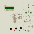
Voltmeter Ammeter Circuit

Notes: Pic without replacing V-1 voltmeter using potentiometer RV2 have to be at the point of +5 V will be set. Then attaching the circuit should be run instead of the pic. By connecting an ammeter in series to the circuit for power adjustment appears on the display until the same current gain adjustment should be made with potentiometer RV3
author: erdemefe
Şifre-Pass: 320volt.com
Published: 2010/08/13 Tags: microchip projects, microcontroller projects, pic16f876 projects, picbasic pro examples

TOP224 SMPS 12V 2A Switch Mode Power Supply Circuit
2A 12V switchmode powersupply SMPS top224 circuit based on integrated control and drive in itself for possessing this integrated circuit is used very little material. Sprint layout prepared by the SMPS circuit and printed circuit sPlan’s scheme drawing prepared by a transformer wire winding info there