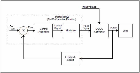
Dc to dc converter circuit based on the powerful but pleasing formulas given all the details about the project is the original microchip application notes. pic16c620 Source code flow diagramm AMS assembly area and it’s a lot more information
DC DC Converter Circuitt Using a PICmicro® Microcontroller

In many applications, a DC/DC Converter is used to produce a regulated voltage or current, derived from an unregulated power supply, or from a battery. Examples of these applications include battery chargers, electronic air purifiers, emergency exit signs, and distributed power systems.
In some of those applications, a dedicated Switched Mode Power Supply (SMPS) Controller IC is used in conjunction with a microcontroller. In other applications, however, a dedicated SMPS Controller IC may be overkill. An alternative approach is to generate a low cost SMPS function in a smart microcontroller, such as the PIC16C620A. This Application Note shows a method of using the microcontroller to perform simple SMPS control functions.
DC / DC INVERTER
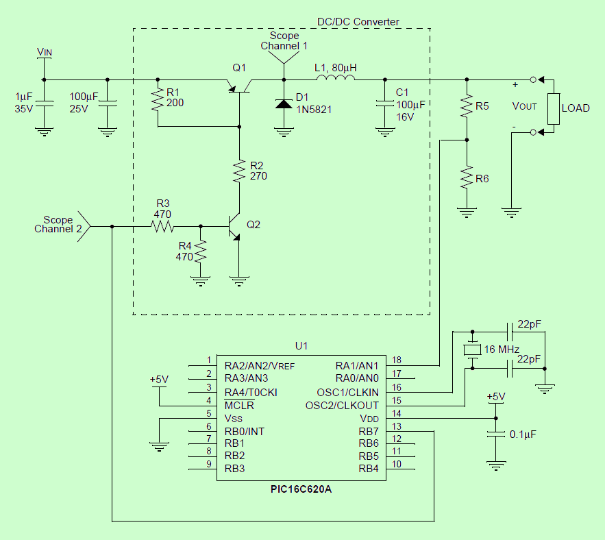
There are several popular DC/DC Converter topologies, such as Boost and Fly-back Converter topologies. The DC/DC Converter used in this example is a Buck (or step-down) Converter topology, also popular, is the Buck Converter, consisting of: transistor Q1, diode D1, inductor L1 and capacitor C1.
Transistor Q2 is used as a level translator. PICmicro device PORTB output to turn Q1 on or off. Application Note AN701 describes how to make a Buck Converter. Works. It also provides a general guide on

PICmicro DC to DC Converter Circuit files:
Şifre-Pass: 320volt.com
30V Adjustable 10A Regulated Power Supply Circuit
Power supply circuit 1.2v – 30 volts adjustable voltage 0 – 10 amps have short circuit protection features adjustable fan control lm337 mosfet buk416 been designing reinforced negative regulator LM358 opamp designed with solid control. Prepared with Eagle’s circuit schematic and PCB drawings
30V Regulated Power Supply Circuit