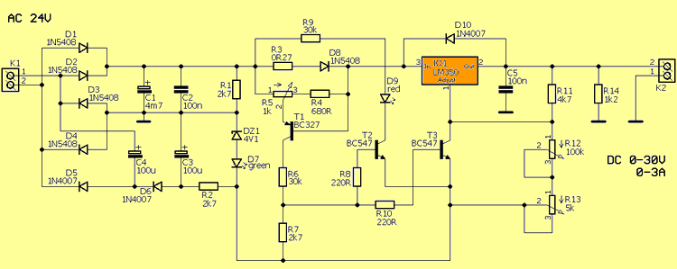
Regulator circuits such as LM317, LM350, which are used for many electronic circuit feeding, do not have current adjustment. In this project, current adjustments are provided with a few additions, and the reference voltage is pulled to zero, and a simple cheap laboratory power supply circuit with a voltage between 0.30V and 0.3A current is made. The author says that the circuit has been working for a long time. I did not add the boxed version of the project because the picture is too small.
24VAC 100W Transformer should be used in power supply. The LM350 regulator integrated should be placed on a sufficiently large cooler or can be used in a small cooler with fan cooling.
R5 (1K) Potentiometer is used to regulate the output current. R12 (100K) If potentiometer output voltage is rough adjustment, R13 (5K) is used for fine adjustment.
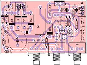
Adjustable power supply circuit has 600dpi PCB drawing in picture format PCB size 86.3 x 46.7mm
Finally, the author says that with 2X12V AC Transformer, it increases the efficiency with manual bypass and used the key for this. For automatic system, see Relayed bypass circuit article for regulated power supplies.
LM350 0-30V 0-3A Power Supply Circuit Diagram

Source: hobbyelektro.eu
FILE DOWNLOAD LINK LIST (in TXT format): LINKS-26643a.zip
Publication date: 2020/04/02 Tags: power electronic projects, power supply circuit, power supply project
LM350 0-30V 0-3A Alimentation de laboratoire
Les circuits de régulation tels que LM317, LM350, qui sont utilisés pour de nombreux circuits électroniques d’alimentation, n’ont pas de réglage de courant. Dans ce projet, des ajustements de courant sont fournis avec quelques ajouts, et la tension de référence est ramenée à zéro, et un simple circuit d’alimentation de laboratoire bon marché avec une tension entre 0,30 V et 0,3 A est réalisé. L’auteur dit que le circuit fonctionne depuis longtemps. Je n’ai pas ajouté la version encadrée du projet car l’image est trop petite.
Le transformateur 24VAC 100W doit être utilisé dans l’alimentation. Le régulateur LM350 intégré doit être placé sur un refroidisseur suffisamment grand ou peut être utilisé dans un petit refroidisseur avec refroidissement par ventilateur.
Le potentiomètre R5 (1K) est utilisé pour réguler le courant de sortie. R12 (100K) Si la tension de sortie du potentiomètre est un réglage approximatif, R13 (5K) est utilisé pour un réglage fin.
Le circuit d’alimentation réglable a un dessin de PCB de 600 dpi au format d’image PCB taille 86,3 x 46,7 mm
Enfin, l’auteur dit qu’avec le transformateur AC 2X12V, il augmente l’efficacité avec le bypass manuel et a utilisé la clé pour cela. Pour le système automatique, voir l’article Circuit de dérivation relais pour les alimentations régulées.