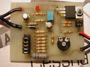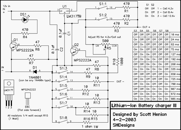
Lithium ion, Lithium polymer charging circuit made with LM317 can provide both current and voltage adjustable 4.2v 8.2v and 12.6v output, that is, 2…3 series connected li-ion batteries can be charged. Since the current setting is gradual, it is easier to use and current setting can be made between 10ma….985ma.
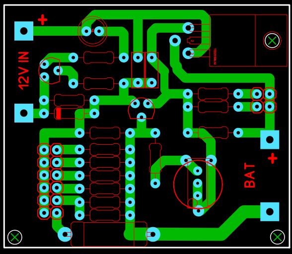
Li-Ion charging circuit PCB drawing designed with Circad-98 program download address: www.holophase.com
Output voltage for single Li-Ion battery will be set as 4.2v, 8.4v for 2 series batteries, 12.6v for 3 series batteries. If charging will be done with 12.6v output, input voltage should be 15V DC, 12V DC is sufficient for others, if possible, 1% tolerance of resistors used in the circuit will give better results
LM317 gets hot since LM317 IC consumes approximately (12-8.4) * 0.3 = 1 Watt with currents starting from 300 mA in 8.4V Battery charging. A heatsink should be attached to LM317 IC to provide maximum current of approximately 980 mA, otherwise it will not work for a long time.
Pay attention to polarity when connecting batteries to the output of the circuit, reverse connection will damage the circuit. The charger is only suitable for Li-Ion and Li-Poly batteries, do not use it for NiCd and NiMh.
The LM317 Li-Ion charging circuit is quite good in this form, both current and voltage adjustable, in fact, a more powerful charging circuit can be made by using lm350 (3 amps) or lm338 (5 amps) instead of lm317 and changing the resistance values on the circuit.
LM317 Li-Ion Li-Poly Charging Circuit Diagram

Bill of Materials
Resistors (1/4w)
R1 470 ohm
R2 470 ohm
R3 470 ohm
R4 470 ohm
R5 470 Trimpot
R6 47 ohm
R7 47 ohm
R8 47 ohm
R9 47 ohm
R10 1k ohm
R11 10 ohm
R12 10 ohm
R13 10 ohm
R14 10 ohm
R15 10 ohm
R16 1 ohm 1 watt
Capacitor
C1 0.1uF polyester
C2 0.1uF polyester
Integrated
U1 LM317T
Diode
D1 1N4001
DS1 Led
Transistor
Q1 2N2222A
Q2 2N2222A
Update: I said that the PCB drawing was prepared with the Circad-98 program, the source drawing file is also there, but the program is a bit useless, I copied the original PCB drawing with the Sprint Layout PCB Program. The source and gerber files were added to the archive. In addition, an arrangement was made for the multi-turn trimpot.

Source: baronerosso.net alternative link:
Şifre-Pass: 320volt.com
Published: 2011/05/17 Tags: battery charger circuit, power electronic projects
Delay-PIC ASM Code Generator
Pic with ASM programs may be useful tools for writers to asm “delay” delay time code to the given value (cycles) automatically calculates and displays based program does not require installation grew 320kb
Delay PIC screenshot