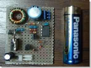
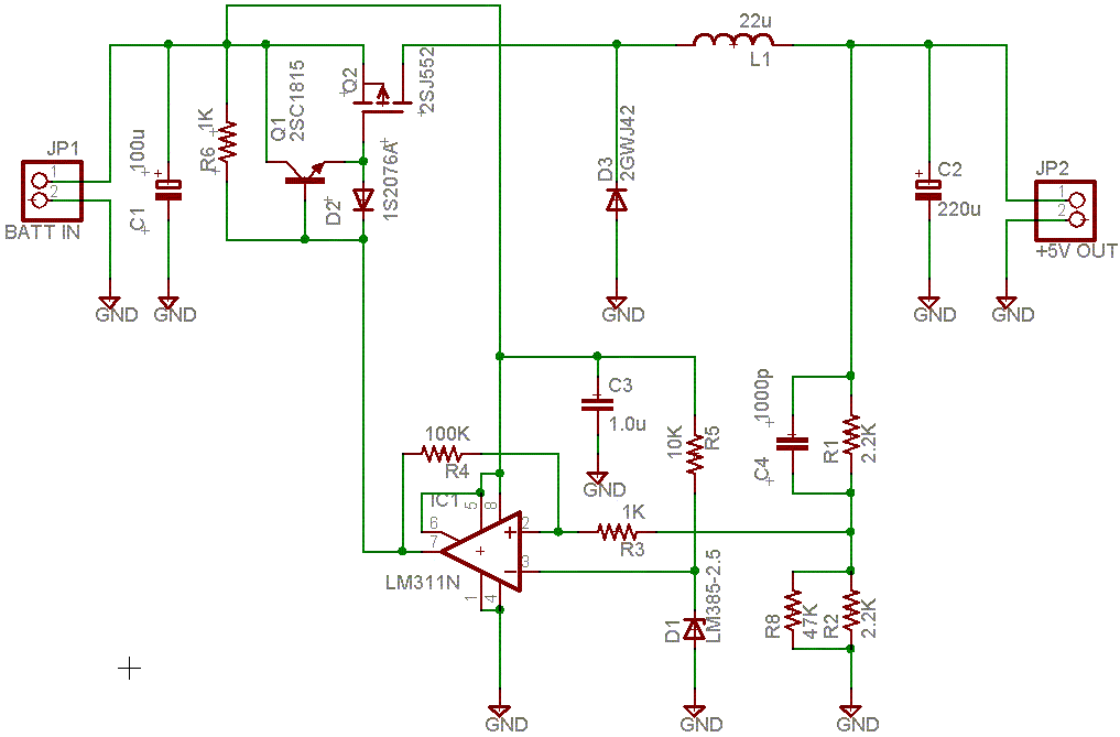
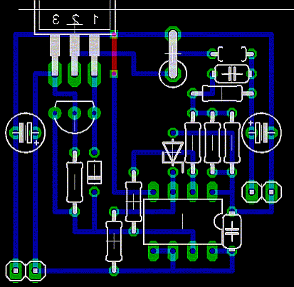
The control of the switching regulated circuit was provided with the lm311, in the tests w-zero3 pda or a similar device was used (I am not entirely sure)
L1 (25uH/2A), R1, R2 (2.2kΩ) This output determines the voltage. Vout = VD1 × (1 + R1/R2) VD1 = 2.5v
C2 (220uF aluminum electrolytic) affects the behavior of the circuit. Low ESR capacitor (like ceramic or OS, laminated parts) ripple can cause more distortion and lower frequency response
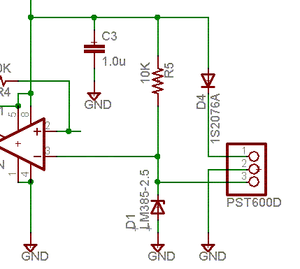
D1 (LM385-2.5) 2.5V constant voltage reference source. REF TL431 can be substituted at the cathode and not directly reducing the current shortage of R5 when at the terminal. Need 1kΩ ~ 2.2kΩ.
5V 2A Switching Regulator Project
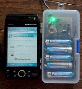
The input voltage of the circuit is provided by connecting 5 Panasonic AA batteries in series.
Published: 2009/04/09 Tags: power electronic projects
Color Sense Circuit LCD PIC16F877 Picbasic Pro
This circuit using a PIC 16F877 microcontroller LCD (Liquid Crystal Display) has been applied on the color sensor. For circuit design and printed circuit board operations and Proteus ISIS Proteus ARES program is used. The operating logic circuits in a closed environment in order of ARD flashing light emitted from the LEDs is based on the influence resistance to change.
PIC16F877 Microcontroller Color Sense Project