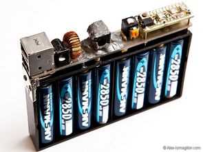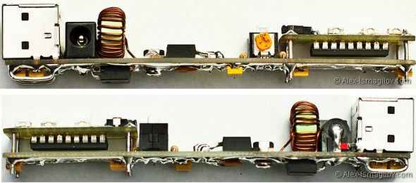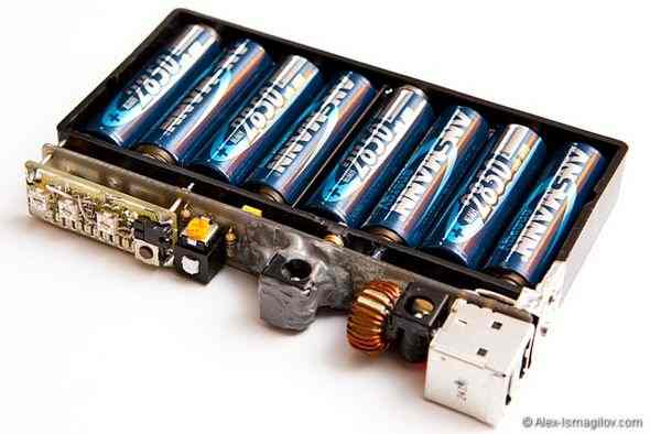
Dc to dc 5 volt converter.. converter circuit LM2678 (5A step-down regulator) based on the layout of the board quite well designed also LM3914 prepared with LED voltmeter Node voltage monitoring is easy In addition to “backup” backup battery has sections 8 AA batteries can be connected. Between 7 …. 40v DC adapter to the DC input jack can be connected subcontracted with 5v devices or devices that can operate via USB portable power supply for the supply of …
Finally Voltmeter prepared with LM3914 circuit is intended as an additional module for printed circuit board pcb circuit separately so that you can use for different projects used instead of the normal LEDs SMD LEDs can also be connected.


It operates at an internally fixed frequency of 260KHz. The output voltage is set by the chain R1, R2, R3. It is set by the resistor R2. Input and output capacitors – tantalum – are selected according to size and for surface mounting, housing – D type. The possible input voltage range of such a converter is from 7 to 40V. At high input voltages, it is necessary to select the input filter capacitors C1-C3 for the required operating voltage. LM2678 allows you to make a circuit with a low-current power switch.
The power input (pin 2) is connected directly to the battery. The drive starts when pin 7 is disconnected from the ground. Inductor L1 is wound on a core of powdered iron in the constructive T50-52B (size 12.7 / 7.7 / 6.35 mm) (inductor from an old PC motherboard made of green-blue marked material No. 52)
The inductance of the choke 33uH is selected according to the nomograms from the microcircuit description (pdf). Throttle manufacturing. Older motherboards have switching converters with coils:
According to the document (“IronPowderCoils.doc” , “IronPowderCoils.xls” ), we determine the parameters of the cores that we managed to find. In my case: Green – blue, outer diameter 12.7 mm and height 6.35 mm. For him A L = 43.5 nH / Vit 2
The inductance of a choke coil wound on a ring core is calculated by the formula: L = A L * N2 . Therefore, the number of turns required for winding is calculated by the formula: N = SQRT (L / A L) = SQRT (33 μ H / 43.5 n H / Vit 2) = 28 Turns. Wire diameter 0.7 mm. It is wound on the coil in a flat layer coil
Schottky Diode (SD1) – MBRB1545CT (45V 15A) (PDF) in D2Pak SMD package (with spare and large heat sink).
Converter printed circuit board, size 120 x 16 mm.
The indicator is designed to operate on 8 1.2V batteries connected in series. It is configured to display voltage in the range of 1.1V (cell discharged) to 1.35V (fully charged). As a result, the input voltage varies from 8.8V to 10.8V.
The characteristics of the microcircuit do not allow measuring the input voltage up to the supply voltage level. Therefore, for simplicity, only half of the input voltage is measured. For this, an input divider is used on resistors R1 + R2 + RT1. In general, they can be replaced with 2 identical fully matched resistors without the possibility of adjustment. After the divider, the input voltage varies from 4.4V to 5.4V.
The LM3914 has an internal adjustable voltage reference. Resistors R3 + RT2 are used for mounting (two chains – for ease of fine-tuning). Resistor RT2 sets the upper limit measured at pin 7 (Ref output) U hi = 5.4V. This voltage is applied to the input of the internal divider of the comparators. The lower limit of the measured voltage will be touched by resistors R4 + RT3. Resistor RT 3 sets the lower limit at pin 4 ( R lo ) at U lo = 4.4V.
Resistor R5 sets the current of the LEDs, which is about 10 times the current through resistor R5. Pin 9 of the LM3914 is used to set the display mode of the display. When power is applied, the LEDs will light up.
Source: alex-ismagilov.com alternative link:
Şifre-Pass: 320volt.com
Published: 2011/07/26 Tags: dc dc converter circuit, power electronic projects
12V DC to DC 5V Converter Circuit USB MC34063
DC to DC converter circuit in the car, car stereo mounted 12-volt battery into the tape used direct voltage of 5v, as reduces switching control IC MC34063 (StepUp Inverting Switching Regulator, Down) used. Input voltage: 8v … 40v-printed circuit board design pcb and the SPLA prepared with regular sprint layout prepared with schema files.